Home

Blog

Blog

  • How do cable specifications impact hybrid electric vehicle performance?
    How do cable specifications impact hybrid electric vehicle performance?
    Jun 15, 2026
    You rely on the right Hybrid Electric Vehicle Cable to optimize your vehicle’s power delivery, safety, and efficiency. Cable specifications play a direct role in how your hybrid electric vehicle performs every day. The type, size, material, and insulation of each hybrid electric vehicle cable affect energy loss, heat management, and long-term durability. You can see how heat resistance, weight, and electromagnetic interference shape the efficiency and safety of every hybrid electric vehicle cable. The insulation material in a hybrid electric vehicle cable determines its temperature rating, which protects your vehicle from overheating and ensures reliability. When you choose a hybrid electric vehicle cable, you also impact the overall weight, which influences range and efficiency. The right hybrid electric vehicle cable withstands operational heat and maintains performance over time.   Hybrid Electric Vehicle Cable Types   You encounter several cable types in hybrid electric vehicles, each designed for a specific role. These cables ensure your vehicle operates safely and efficiently, even under demanding conditions. EV Battery Cables: You use these to transmit power between the battery pack and the electric systems. They handle high electrical currents and voltages, often reaching hundreds or even over 1,000 volts. 
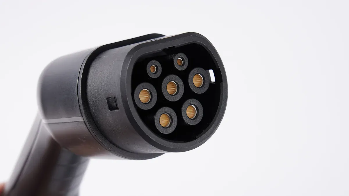
EV Charging Cables: These connect your vehicle to external electrical sources. You rely on them for both home and public charging, with variations like Type 1 and Type 2 for different charging stations. 
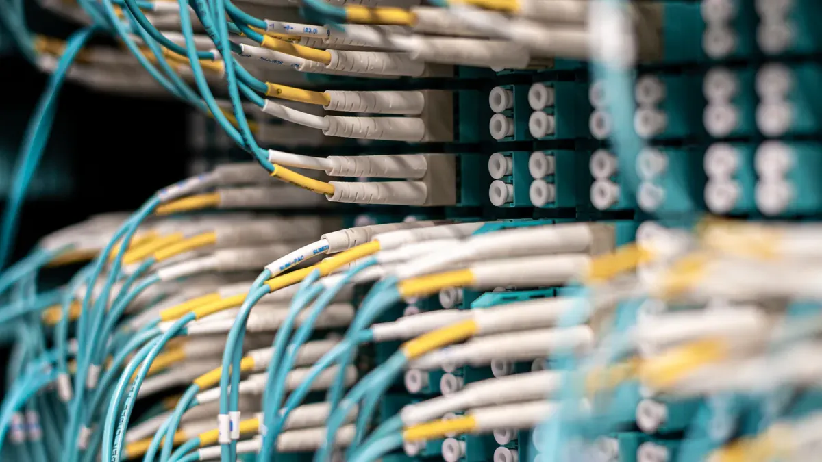
Signal Cables: These manage communication between electronic control units, sensors, and actuators. You depend on them for accurate data transmission and system coordination. Hybrid Cables: These integrate multiple functionalities, such as power and signal transmission, into a single cable assembly. You benefit from reduced weight and simplified installation.   Power Cables   Power cables form the backbone of your hybrid electric vehicle’s electrical system. You find them in two main categories:   High Voltage   High voltage power cables deliver energy from the battery to the electric motor and other high-power components. You often see three large-diameter wires used for motor power, ensuring efficient energy transfer and minimizing losses. These cables must withstand high temperatures and mechanical stress during operation.   Low Voltage   Low voltage power cables supply energy to auxiliary systems, such as lighting, infotainment, and control modules. You need these cables to maintain stable performance and protect sensitive electronics from voltage fluctuations.   Signal Cables   
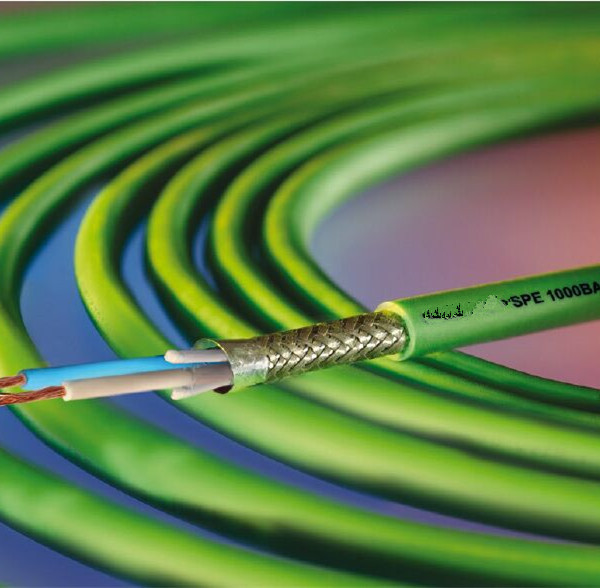
Signal cables play a critical role in your vehicle’s communication network. They transmit control signals, sensor data, and feedback between various modules. You rely on their shielding to prevent electromagnetic interference, which ensures accurate and reliable operation of safety and performance systems.   Vibration-Proof Heat Resistant Cable   You face harsh environments in hybrid electric vehicles, including constant vibration and elevated temperatures. The Vibration-proof Heat Resistant Cable addresses these challenges by combining flexibility, durability, and superior heat resistance. You can use these cables in areas exposed to engine heat or frequent movement, which helps maintain stable charging and power delivery. Their robust construction reduces the risk of insulation failure and extends the service life of your vehicle’s wiring system. Tip: When selecting cable types for your hybrid electric vehicle, always consider the specific requirements of each application. Proper cable selection enhances charging efficiency, safety, and long-term reliability.   Electric Vehicle Charging Cables   You interact with several types of charging cables every time you connect your hybrid or electric vehicle to a charging station. Understanding the differences between these cables helps you make informed decisions about charging infrastructure and ensures your vehicle charges safely and efficiently.   Type 1 and Type 2 Cables   You often encounter Type 1 and Type 2 cables at public charging stations and home charging points. Type 1 cables use a single-phase connection, which suits many hybrid electric vehicles in North America and Japan. Type 2 cables, on the other hand, support both single-phase and three-phase charging. You find Type 2 cables as the standard across Europe, making them compatible with almost all electric vehicles and hybrid models. Type 2 cables offer flexible charging speeds, ranging from 3.7 kW up to 22 kW, which allows you to select the right charging point for your needs. The combined charging system and chademo connector also play a role in fast charging, but Type 2 remains the most widely adopted for everyday use. Here is a comparison to help you understand the differences: Feature Type 2 Chargers Type 3 Chargers Compatibility Widely compatible with almost all EVs due to the standard Type 2 socket. Limited compatibility; only a few EV models are equipped with Type 3 sockets. Charging Speed Offers power options from 3.7 kW to 22 kW, suitable for various charging needs. Capable of delivering up to 22 kW, comparable to Type 2 chargers. Adoption Standard in Europe and widely used at commercial charging stations. Limited adoption, mainly in French-speaking countries. Communication Protocol Uses IEC 61851-1 Mode 2 or Mode 3 protocol, enabling advanced features like monitoring and remote control. Uses IEC 61851-1 Mode 3 protocol, less supported by EV manufacturers. You see that Type 2 cables dominate the market due to their compatibility and charging speed. You also notice that the sae j1772 connector is common in North America, while the combined charging system and chademo connector support dc fast charging at many charging stations.   Mode 3 Charging Cables   You use Mode 3 charging cables at dedicated charging stations and charging points. These cables connect your vehicle directly to the charging infrastructure, providing advanced safety features and communication protocols. Mode 3 supports both tethered cables and untethered cables, giving you flexibility at public and private charging points. Tethered cables remain attached to the charging station, while untethered cables allow you to carry your own cable and connect to different charging stations. You benefit from Mode 3’s ability to handle dc fast charging, which reduces charging time and increases convenience.   Cable Structure and Insulation   You rely on electric vehicle charging cables with robust structure and insulation to ensure safety and performance. The insulation provides electrical isolation, which prevents shocks during charging. It also offers mechanical protection, shielding the cable from physical damage and environmental factors like UV light and moisture. High-temperature resistance materials, such as 125℃ irradiation cross-linked insulation, maintain cable integrity under the heat generated by dc fast charging. These materials also resist aging and mechanical wear, extending the lifespan of your charging cables. High-temperature resistance keeps your cables safe during dc fast charging. Aging resistance protects against UV rays and moisture at outdoor charging stations. Mechanical durability ensures reliable performance at every charging point. You can enhance your charging experience by choosing electric vehicle charging cables with advanced insulation and multi-layer design. For applications requiring even higher temperature resistance, you may consider 150°C and 200°C Fluoroelastomer wire, which delivers exceptional durability and safety for demanding charging environments.   Conductor Material   
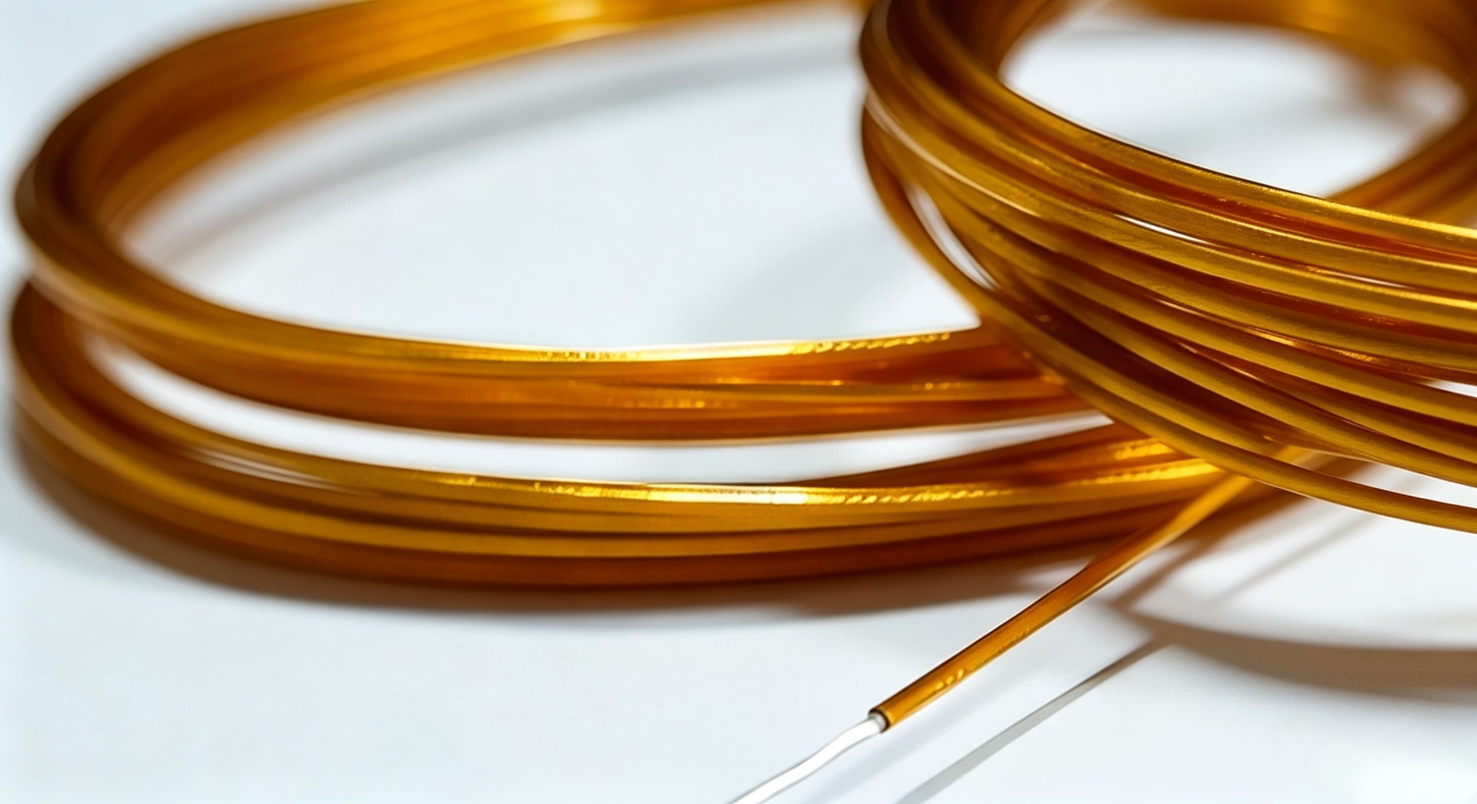
You make a critical choice when selecting the conductor material for your hybrid electric vehicle cables. The conductor determines how efficiently electricity flows, how much heat the cable generates, and how much weight your vehicle carries. Two main options dominate the industry: copper and aluminum.   Copper vs Aluminum   Conductivity   You want your cables to deliver power with minimal loss. Copper stands out for its superior electrical conductivity. Aluminum, while lighter, does not match copper’s ability to carry current as efficiently. The table below compares the two materials: Property Copper (Cu) Aluminum (Al) Conductivity (IACS) 100% ~61% Resistivity (Ω·mm²/m) 0.0172 0.0282 You see that copper offers the highest conductivity, which means less energy loss and lower heat generation. Aluminum’s higher resistivity means you need a larger cross-sectional area to achieve the same performance as copper. This difference impacts both efficiency and cable design.   Weight   You also need to consider the weight of your vehicle’s wiring. Aluminum provides a significant advantage here: Aluminum weighs about one-third as much as copper, which helps reduce the overall weight of your vehicle. Lighter wiring can improve your vehicle’s range and efficiency because less energy is required to move the vehicle. Many engineers use aluminum for busbars and certain wiring components, achieving up to 50% weight savings compared to copper. You benefit from these weight reductions, especially in hybrid electric vehicles where every kilogram counts.   Material Purity   Imagine two roads: one smooth and freshly paved, and another filled with small rocks and debris. A car can travel on both, but the smooth road allows for faster, more consistent movement. Electricity behaves the same way in conductors. High-purity materials provide a clear path for electrons, while impurities act like obstacles, increasing resistance and wasting energy. You should always look for high-purity conductor materials in your hybrid electric vehicle cables. Purity directly affects resistance. Impurities disrupt the flow of electrons, causing more heat and energy loss. Over time, this extra heat stresses the insulation, which can lead to premature wear or even electrical faults. Impurities also accelerate corrosion and fatigue, reducing the long-term reliability of your cables. Manufacturers measure purity using industry standards such as conductivity tests and chemical analysis. For example, copper conductors often come in purities like 99.90%, 99.95%, or even 99.999%. Even small differences in purity can lead to noticeable changes in conductivity, heat generation, and cable lifespan. You ensure the best performance and durability by choosing cables with the highest available purity.   Cable Size   You make critical decisions about cable size when designing or maintaining a hybrid electric vehicle. The right cable size ensures safe, efficient charging and reliable power delivery. You must consider several factors, such as conductor standards, voltage range, and the environment where the cable operates. When you select a cable for charging, you look at the working voltage, current, and temperature rise. You also compare the peak current and duration with the cable’s performance curve. This process helps you match the cable size to the demands of your charging system.   Current Capacity   You need to match the cable’s current-carrying capacity to the charging requirements of your vehicle. If you choose a cable that is too small, you risk overheating and energy loss during charging. If you select a cable that is too large, you add unnecessary weight and cost. You follow industry standards like LV216-1/2 and ISO19642 to guide your choices. These standards help you verify the working voltage, usually below 1000V DC, and select the right diameter for your charging cables.   Energy Loss   You want to minimize energy loss during charging. When you use a cable with the correct size, you reduce resistance and keep energy loss low. If the cable is too thin, resistance increases, and you lose more energy as heat. This loss affects the efficiency of your charging process and can shorten the lifespan of your vehicle’s electrical system. You always check the effective working current and ensure the cable can handle the peak current during charging.   Heat Generation   You must control heat generation in your charging cables. Excessive heat can damage insulation and reduce cable life. You select cable sizes based on temperature rise and current-carrying capacity. You also ensure that the fuse blows before the cable reaches its smoke point. This approach protects your vehicle during high-current charging events. You rely on cables with advanced insulation, such as those found in Vibration-proof Heat Resistant Cable, to withstand the heat produced during fast charging. Tip: Always monitor the temperature of your charging cables during operation. Consistent overheating signals the need for a larger cable size or improved insulation.   Impact on Vehicle Weight   You balance cable size with vehicle weight to optimize charging efficiency and performance. When you use higher voltage systems, such as 48V, you can select smaller cables for charging. These cables weigh less and use less copper than traditional 12V wires. For example: 48V charging wires have about 10% of the diameter and weight of 12V wires. Smaller charging cables reduce the overall weight of your vehicle. Lower weight improves thermal efficiency and enhances vehicle performance during charging. You see that every kilogram saved in cable weight can extend your vehicle’s range and improve charging speed. You also reduce material costs and make your vehicle more efficient. When you choose the right cable size for charging, you achieve a balance between safety, performance, and weight. You can further enhance your charging system by selecting cables with high-temperature insulation, such as 150°C and 200°C Fluoroelastomer wire. These cables maintain performance even during intense charging sessions and demanding environments.   Insulation and Heat Resistance   You depend on advanced insulation and heat resistance to ensure your hybrid electric vehicle cables perform reliably under demanding conditions. Insulation materials protect against electrical faults, mechanical damage, and environmental hazards. High-performance insulation also maintains cable integrity when exposed to elevated temperatures and vibration.   Fluoroelastomer Wire   
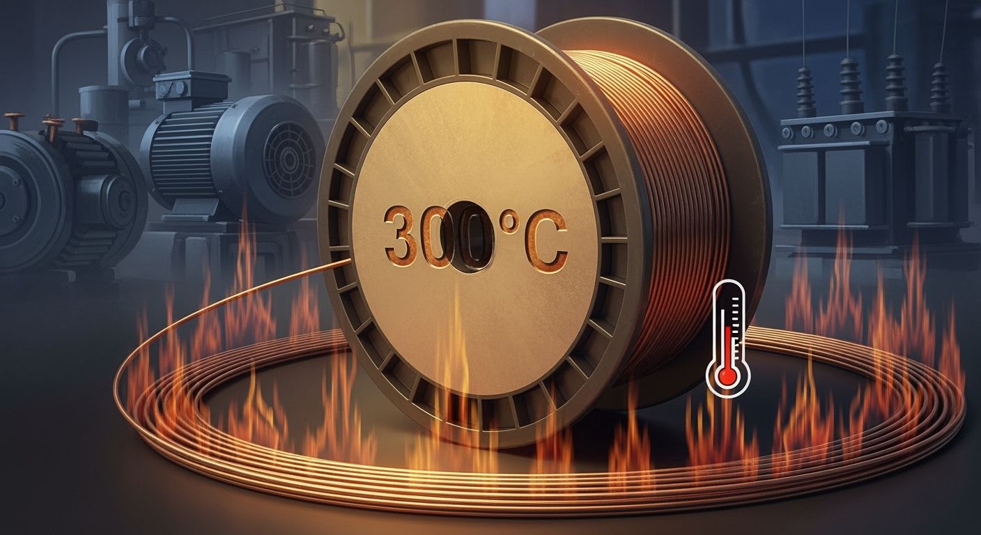
High Temperature Performance   You encounter extreme heat in hybrid electric vehicle powertrains, especially near engines and battery packs. Insulation materials with higher temperature ratings deliver superior durability and safety. The table below compares common insulation materials used in hybrid electric vehicle cables: Property PVC TPU Irradiation Cross-Linked Max Operating Temp ~70℃ ~90℃ 125℃ continuous UV Resistance Low Medium High Flexibility at Cold Poor Good Excellent Mechanical Strength Low Medium High Environmental Compliance Halogenated Variable Halogen-Free Cost Low Medium Higher (but long-lasting) Insulation materials rated for 125°C or higher, such as irradiation cross-linked compounds, resist degradation and maintain structural integrity under high current loads. Lower-rated materials like PVC can soften and lose strength at elevated temperatures, increasing fire risk and reducing cable lifespan. You achieve even greater heat resistance with fluoroelastomer wire. AFLAS fluoroelastomers withstand temperatures up to 200°C, making them ideal for hybrid electric vehicle applications. FEPM fluoroelastomers also deliver long-term durability in high-temperature environments. These materials ensure reliability where thermal stress is constant. AFLAS fluoroelastomers operate reliably at temperatures up to 200°C. FEPM fluoroelastomers provide lasting performance in high-heat zones. Fluoroelastomer insulation remains nonflammable, supporting safety in electric and hybrid vehicles.   Durability   You require cables that last through years of operation. Fluoroelastomer wires resist chemical exposure, mechanical abrasion, and thermal cycling. Their nonflammable nature protects your vehicle from fire hazards. You benefit from their ability to maintain flexibility and insulation integrity, even after repeated heating and cooling cycles. Choose fluoroelastomer wire for critical areas where heat and durability matter most. You secure long-term reliability and reduce maintenance needs.   Vibration-Proof Features   You face constant vibration in hybrid electric vehicles, especially near motors and suspension systems. Vibration-proof features protect cable integrity and prevent insulation failure. Hoonsun seals provide effective vibration damping and exceptional resistance to high temperatures. These seals offer excellent cable management and structural protection, which are essential for maintaining performance under vibration. Secondary locking features enhance vibration resistance. Sealing gaskets deliver environmental protection (IP67+), ensuring durability. Shielded, compact connectors maintain signal integrity during high-vibration operation. Flexible cable materials like silicone and advanced TPE blends withstand frequent movement and vibration. Spiral and recoilable cable designs offer shape memory and elastic recovery, further improving vibration resistance. You maintain cable integrity by selecting cables with robust vibration-proof features. These designs ensure stable performance and reduce the risk of electrical faults. For the most demanding environments, you can rely on 150°C and 200°C Fluoroelastomer wire to deliver unmatched heat resistance and durability. This choice supports optimal performance and safety in hybrid electric vehicles.   EV Charging Connectors   You interact with ev charging connectors every time you charge your hybrid electric vehicle. These connectors serve as the critical link between your vehicle and the charging station. The right connectors ensure that energy flows safely and efficiently, supporting the overall performance of your vehicle. When you select a Hybrid Electric Vehicle Cable, you also need to consider the compatibility and quality of the connectors attached to it.   Connector Quality   The quality of ev charging connectors directly affects the reliability and safety of your charging system. High-quality connectors provide a secure and stable connection, which is essential for efficient energy transfer.   Secure Connections   You depend on connectors to create a solid link between the charging cable and your vehicle. The control module checks the connectors before charging begins. If the connectors do not latch properly, the system will disable the connection to prevent risks such as arcing or overheating. This process protects you and your vehicle from dangerous situations. Reliable connectors also help maintain a consistent flow of electricity, reducing the chance of interruptions during charging. Connectors play a crucial role in the charging process by ensuring proper attachment. The system checks connectors for readiness before allowing energy transfer. If a latch slips or a connector fails, the system stops charging to prevent hazards.   Maintenance   You need to maintain your ev charging connectors to ensure long-term performance. Regular inspection helps you spot signs of wear, corrosion, or damage. Clean connectors allow for better contact and reduce resistance, which improves charging efficiency. If you notice any issues, replace the connectors promptly to avoid safety risks. Using a Vibration-proof Heat Resistant Cable can also help, as these cables and their connectors withstand harsh environments and frequent use. Inspect connectors for physical damage or corrosion. Clean connectors regularly to maintain optimal contact. Replace worn or damaged connectors to ensure safety.   Impact on Performance   The performance of your hybrid electric vehicle depends on the quality and condition of the ev charging connectors. These connectors form part of the Electric Vehicle Supply Equipment (EVSE), which includes cables and protective devices. EVSE ensures standardized and safe energy transfer between the power source and your vehicle. Rigorous testing and compliance with industry standards guarantee that connectors deliver reliable performance. When you use high-quality connectors, you experience faster charging times and fewer interruptions. Poor-quality connectors can cause energy loss, overheating, or even system failure. You should always choose connectors that meet strict safety and durability standards. For demanding environments, consider using 150°C and 200°C Fluoroelastomer wire with compatible connectors to achieve the best results. Tip: Always match your connectors to your vehicle’s requirements and charging environment. This practice ensures optimal performance and extends the lifespan of your charging system.   Performance Concerns   Energy Efficiency   You strive for maximum energy efficiency in every hybrid electric vehicle. Cable specifications play a crucial role in how efficiently your vehicle transfers power during charging and operation. When you select cables with high conductivity and optimal size, you minimize energy loss. Copper conductors deliver superior performance, but you must balance weight and flexibility. Aluminum offers lighter alternatives, yet requires larger diameters to match copper’s efficiency. You also need to consider insulation materials. Advanced insulation reduces resistance and prevents unnecessary heat buildup. When you use cables with high-purity conductors and robust insulation, you ensure that more energy reaches the motor and battery, rather than dissipating as heat. This approach improves your vehicle’s range and reduces charging time. Tip: Always match cable specifications to your vehicle’s charging requirements. Proper selection enhances energy efficiency and supports faster charging cycles.   Heat Management   You face significant heat management challenges when operating hybrid electric vehicles. Cable selection directly impacts how well your vehicle handles thermal stress during charging and high-power operation. Common challenges include: Managing heat exposure in cables near battery packs and motors Selecting appropriate insulation materials for high-temperature zones Ensuring flexibility and durability under continuous thermal stress You must choose insulation materials rated for the expected temperature range. Here is a comparison of common insulation types and their temperature ratings: Insulation Material Max Operating Temperature PVC 90° to 105°C Thermoplastic Polyurethane (TPU) Up to 125°C Cross-linked Polyethylene (XLPE) Up to 125°C Irradiation XLPE Up to 150°C Silicone & Cross-linked Fluoroelastomers (XLFEs) Up to 200°C You rely on advanced insulation materials to improve heat management. Ceramic fiber holds a significant share of the electric vehicle insulation market due to its exceptional heat resistance and fire protection. Silicone rubber offers flexibility and strong thermal resistance, supporting long service life and enhancing safety in high-voltage environments. Thermal interface materials improve thermal conductivity, preventing overheating in battery packs and power electronics. When you select cables with high-temperature insulation, such as 150°C and 200°C Fluoroelastomer wire, you protect your vehicle from thermal events and ensure reliable charging performance. These materials withstand extreme heat and maintain structural integrity, supporting critical safety features. Note: Effective heat management extends cable lifespan and reduces maintenance needs. Always verify insulation ratings before installing cables in high-temperature areas.   Durability   You demand durability from every cable in your hybrid electric vehicle. Environmental factors such as temperature, vibration, humidity, and mechanical stress challenge cable longevity. Industry standards, including ISO 16750-3 and ISO 16750-4, address mechanical and climatic loads. These standards require cables to withstand vibration, mechanical shock, humidity, dust, corrosion, and ice. You encounter combined humidity and vibration tests that simulate real-world conditions. Temperature testing ranges from -45°C to 50°C, with higher thresholds for cables near engines or exposed to sunlight. Environmental tests verify cable effectiveness and safety at both vehicle and subsystem levels. You achieve greater durability by selecting cables with robust insulation and vibration-proof features. Flexible materials, such as silicone and fluoroelastomers, maintain performance under repeated movement and thermal cycling. When you use cables like Vibration-proof Heat Resistant Cable, you ensure stable charging and protect against insulation failure. Tip: Choose cables tested for vibration and climatic loads. This practice guarantees long-term durability and supports essential safety features in hybrid electric vehicles.   Safety   You must prioritize safety when selecting cables for hybrid electric vehicles. The right Hybrid Electric Vehicle Cable protects you from electrical hazards and ensures your vehicle operates reliably in all conditions. Industry standards require cables to pass rigorous tests before they reach your vehicle. These tests confirm that each cable can withstand the harsh environments and high voltages found in modern hybrid systems. Testing Category Purpose Thermal Aging Tests Evaluate material performance after prolonged heat exposure (e.g., 125°C for 3,000+ hours). Dielectric Breakdown & Insulation Resistance Tests Measure resistance to electrical breakdown at high voltages (1,000V to 5,000V). Flame Propagation Tests Ensure materials do not contribute to fire spread or emit toxic smoke (IEC 60332-1, UL 94). Cold Flexibility and Abrasion Tests Assess durability in winter conditions and during vibrations. Chemical Resistance Testing Simulate exposure to various automotive fluids. Water Spray and Condensation Tests Critical for cables routed underfloor or near HVAC systems. You depend on these tests to guarantee that your vehicle’s wiring will not fail under stress. For example, flame propagation tests ensure that cables do not spread fire or release harmful smoke. Dielectric breakdown and insulation resistance tests confirm that cables can handle high voltages without shorting or leaking current. Cold flexibility and abrasion tests check that cables remain durable during winter driving and constant vibration. Automotive engineers also use advanced systems to monitor cable integrity. The High Voltage Interlock Loop (HVIL) checks the condition of high-voltage modules, cables, and connectors. This system powers down the high-voltage circuit if it detects a fault. HVIL prevents electric shock by ensuring that voltage levels are safe before you or a technician can touch any components. You benefit from this automatic protection every time you drive or service your vehicle. HVIL monitors the entire high-voltage system for faults. It disconnects power instantly if a problem appears. You avoid electric shock because HVIL ensures safe voltage levels before contact. You should also consider the cable’s ability to resist fire, chemicals, and water. Hybrid vehicles often operate in challenging environments, such as wet roads or near engine compartments. A Vibration-proof Heat Resistant Cable provides extra protection against heat, vibration, and moisture. This type of cable maintains its structure and insulation even when exposed to harsh conditions, reducing the risk of short circuits or fire. When you select cables with high-quality insulation, you further improve safety. Materials like 150°C and 200°C Fluoroelastomer wire offer outstanding resistance to heat and chemicals. These wires do not burn easily and do not emit toxic smoke, which helps protect you and your passengers in the event of a fire. You can trust these advanced materials to keep your vehicle’s electrical system secure and reliable. Tip: Always choose cables that meet or exceed industry safety standards. This decision protects you, your vehicle, and everyone on the road.   You drive performance, safety, and reliability by selecting the right cable specifications for hybrid electric vehicles. You optimize charging efficiency with advanced conductor materials and precise cable sizing. You improve charging safety by using insulation that withstands heat and vibration. You benefit from innovations like thermally conductive insulation, nanomaterial-enhanced conductors, and smart cables that monitor charging conditions. You rely on co-extrusion techniques for compact cable designs and enhanced charging durability. You achieve optimal charging operation by prioritizing cable quality in every charging system. You secure long-term charging reliability with 150°C and 200°C Fluoroelastomer wire.       FAQ What makes a Hybrid Electric Vehicle Cable different from standard automotive cables? You use a Hybrid Electric Vehicle Cable because it handles higher voltages and currents. This cable supports efficient charging, resists heat, and ensures safety. Standard automotive cables cannot meet the demands of hybrid systems or advanced charging requirements. How do I choose the right cable for fast charging? You select cables rated for your vehicle’s maximum charging current and voltage. Look for robust insulation and heat resistance. Fast charging generates more heat, so you need cables that maintain performance and safety during rapid charging cycles. Why is insulation important for charging cables? Insulation protects you from electric shock and prevents short circuits during charging. It also shields the cable from heat and environmental damage. High-quality insulation ensures your charging system remains safe and reliable, even under heavy use. Can vibration affect charging cable performance? Yes, vibration can cause wear and insulation failure over time. You reduce this risk by using a Vibration-proof Heat Resistant Cable. This cable maintains stable charging performance, even in areas exposed to constant movement or engine vibration. What temperature rating should I look for in charging cables? You should choose cables with a temperature rating that matches your vehicle’s charging environment. For demanding applications, 150°C or 200°C ratings offer superior protection. 150°C and 200°C Fluoroelastomer wire ensures your charging cables withstand extreme heat. How often should I inspect my charging cables? You should inspect your charging cables regularly for signs of wear, damage, or corrosion. Frequent checks help you catch problems early and maintain safe charging. Replace cables immediately if you notice any defects. Do cable connectors impact charging efficiency? Yes, connectors play a key role in charging. Secure, high-quality connectors ensure stable current flow and reduce energy loss. Poor connectors can cause overheating or interruptions during charging, so always use connectors that match your cable and vehicle requirements. Are there standards for charging cable safety? You benefit from industry standards that set requirements for charging cable safety. These standards cover insulation, heat resistance, and durability. Following them ensures your charging cables deliver reliable performance and protect you during every charging session.
    Read More
  • What Are The Key Cable Types For Electronic Products And Their Practical Applications?
    What Are The Key Cable Types For Electronic Products And Their Practical Applications?
    Jun 09, 2026
      You often work with electronic devices that require different c ables for power, charging, and data transfer. The most Useful Cables include: USB-C to USB-A Cable – Connects modern devices to older computers or chargers. Multi-Charging Cable – Supports USB-C, Lightning, and Micro USB for versatile charging. HDMI Cable – Delivers high-quality audio and video between devices. Micro USB Cable – Powers and syncs many small electronics. USB-C to HDMI or DisplayPort Cable – Links devices to external displays. Lightning Cable – Charges and syncs Apple devices. Knowing the most useful cables helps you pick the right cable for your specific device and application. Key Takeaways Choose cables based on device compatibility and performance needs. Use shielded cables to minimize interference in high-EMI environments. Select fiber optic cables for high-speed and long-distance data transfer. Most Useful Cables for Electronics Essential Cable Types Overview You interact with many cable types when working with electronic products. Industry experts highlight these as the most useful: Power cord: Delivers electricity to computers, monitors, and appliances. HDMI cable: Transfers high-definition video and audio for multimedia devices. USB cable: Connects and powers smartphones, tablets, and laptops. Audio cable: Sends sound signals to headphones, speakers, and sound systems. Charging cable: Powers portable electronics and wearables. The table below shows the main uses for each essential cable type: Cable Type Main Uses Power Cord Computers, monitors, printers, household appliances, portable electronics HDMI Cable TVs, projectors, gaming consoles, home theater systems USB Cable Smartphones, tablets, laptops, external hard drives, printers Audio Cable Headphones, speakers, professional sound systems, home theater setups Telephone Cable Landline phones, DSL internet, intercom systems Charging Cable Smartphones, tablets, laptops, wearable devices Choosing the Right Cable You need to consider several factors when choosing the right cable for your device. Start by checking protocol support and speed ratings. Look for clear labels such as “USB 3.2 Gen 2” or “HDMI 2.0” to match your performance needs. Pay attention to cable length, as longer cables can reduce signal quality. Select cables with strong build quality and strain relief to prevent damage. Certification and compatibility matter for safety and reliability. Environmental conditions, such as heat or interference, also affect your choice. In high-temperature sensing or control applications, a High Temperature Sensor Cable can help maintain stable performance. For network connections, always use cables that meet the latest standards to ensure stable performance. By focusing on these criteria, you make choosing the right cable simple and effective for any application. Power Cable Types Standard Power Cables You encounter standard power cables every day when you use computers, monitors, and office equipment. The IEC C13/C14 cable is one of the most common choices for these devices. The C13 connector plugs into your device, while the C14 connects to the power source. This cable supports up to 10 Amps and 240V, making it safe for a wide range of electronics. Detachable power cords, also called line cords, offer flexibility because you can easily replace them if damaged. Always check the voltage and amp ratings, connector type, and certifications before selecting a cable for your device. Testing and validation are critical to ensure cable assemblies meet performance requirements. Electrical tests like continuity and insulation resistance confirm operational integrity, while mechanical tests verify durability under physical stress. Environmental tests assess performance in challenging conditions, ensuring reliability in various applications. The National Fire Protection Association (NFPA) maintains standards that impact cable selection, particularly regarding fire safety. NFPA 70 sets baseline requirements for flame resistance, while NFPA 262 evaluates flame propagation height. Fire alarm cables must comply with NFPA 72 to ensure functionality during a fire. Specialized standards like NFPA 79 for industrial machinery and NFPA 99 for healthcare facilities dictate specific cable requirements relevant to their applications. UL certifications ensure safety benchmarks like fire resistance and insulation performance. RoHS compliance ensures no hazardous materials are used in cable designs. Specialty Power Cables For demanding environments, you need specialty power cables that deliver advanced performance. The ARX-9 FRW Cable and High Tensile Flexible NBR EPDM Rubber Cable stand out for their durability and resistance to harsh conditions. The table below highlights their key characteristics: Characteristic ARX-9 FRW Cable High Tensile Flexible NBR EPDM Rubber Cable Temperature Range -40 to 200°C Suitable for wet and dry environments Short Circuit Overload Up to +300°C Not specified Current Carrying Capacity High Not specified Resistance High resistance to thermal pressure, chemicals, hydrolysis, and weathering Not specified Flame Retardant Yes (UL VW-1, FT4, FT6) Not specified Flexibility Flexible minimum outer diameter Not specified Applications Motor winding, pump cables, marine and industrial applications General use in wet and dry environments You can also choose the CITCABLE Flexible Fluoropolymer Cable for projects that require exceptional weather, heat, and chemical resistance. This cable performs reliably in automotive, marine, and industrial machinery, even in extreme conditions. When you select a specialty cable, always match its features to your application for maximum safety and performance. Data and Network Cables Ethernet and Network Cables You rely on ethernet cables to build a stable and fast network for your devices. These cables connect computers, routers, switches, and servers, forming the backbone of most wired networks. You find several categories, such as Cat5e, Cat6, Cat6a, Cat7, and Cat8, each offering different speeds and shielding levels. Ethernet cables support high-speed data transfer, reduce interference, and ensure reliable communication for home and office internet, gaming consoles, and smart TVs. Tip: Choose a cable category that matches your speed requirements and device compatibility. Here is a comparison of popular ethernet cable types: Cable Type Max Data Transmission Max Bandwidth (MHz) Max Distance Cat5e 1 Gbps 100 MHz 100m Cat6 10 Gbps (up to 55m) 250 MHz 100m (1 Gbps) Cat6a 10 Gbps 500 MHz 100m Cat7 10 Gbps 600 MHz 100m Cat7a 40 Gbps (limited distance) 1,000 MHz 30m Cat8 40 Gbps 2,000 MHz 30m You use network cables for structured connectivity in IT infrastructure, data centers, and video conferencing. Fiber optic cables also play a role in high-speed data transmission, especially for long distances and environments with electromagnetic interference. USB Cable Types You encounter several USB cable types when connecting peripherals and charging devices. Each type serves a specific purpose: USB Type-A: Standard connector for PCs and laptops. USB Type-B: Used for printers and some external drives. USB Mini-B: Found in older cameras and early smartphones. USB Micro-B: Common in Android phones and portable electronics. USB Type-C: Modern, reversible connector for fast data and power delivery. The table below summarizes the main differences between USB versions: USB Version Speed/Transfer Rate Power Max Cable Length USB 1.1 12 Mbit/s N/A 3 Meters USB 2.0 480 Mbit/s 5V, 1.8A 5 Meters USB 3.0 5 Gbit/s 5V, 1.8A 3 Meters USB 3.1 10 Gbit/s 20V, 5A 3 Meters USB 4.0 40 Gbit/s 100W N/A You benefit from USB Type-C’s versatility, which supports both high-speed data transfer and power delivery for modern devices. Audio and Video Cable Types HDMI and DisplayPort Cables You often use hdmi cables and dvi cables to connect your devices for high-quality video and audio. Hdmi cables work with TVs, monitors, projectors, gaming consoles, and home theater systems. DisplayPort cables provide another option, especially for professional and gaming setups. Both hdmi and DisplayPort support high resolutions and refresh rates, but their features differ. The table below compares the main specifications of hdmi and DisplayPort cables: Specification HDMI 2.0 HDMI 2.1 DisplayPort 1.4 DisplayPort 2.0 Bandwidth 18 Gbps 48 Gbps 32.4 Gbps 77.37 Gbps Resolution 4K at 60Hz 4K at 120Hz, 8K at 60Hz 4K at 120Hz, 8K at 60Hz 8K at 120Hz, 16K at 60Hz Multi-Monitor Limited Limited Supports MST Supports MST VRR Support Yes Yes Yes Yes G-SYNC Support No No Yes Yes Hdmi cables are more common in consumer electronics, while DisplayPort excels in multi-monitor setups. Dvi and dvi cables still appear in older monitors and projectors, but hdmi cables offer broader compatibility and advanced features. Audio Cables You rely on audio cables to connect headphones, speakers, and sound systems. The most common types include 3.5mm, RCA, and XLR cables. Each cable type serves a unique purpose in audio setups. Cable Type Key Features Applications 3.5mm Versatile, widely used, compatible with various devices Headphone connection, auxiliary input, gaming headsets, home theater systems RCA Two connectors (red and white), bridges different audio devices Connecting DACs to amps, DJ equipment, older audio gear XLR Locking mechanism, rubber insulation, clear signal transmission Microphones, PA systems, stage speakers, DMX lights You should choose the right cable based on your device and sound quality needs. Hdmi cables can also transmit audio, making them a flexible choice for home theaters. Coaxial Cable Types TV and Internet Applications You rely on coaxial cables for many home and business electronic setups. These cables play a vital role in delivering television and internet services. Most TV and internet installations use coaxial cables with a 75-ohm impedance. RG-6 and RG-59 are the most common types for transmitting audio and video signals. RG-6 stands out for high-definition and ultra-high-definition content because it offers lower signal loss over longer distances. Tip: Choose RG-6 for modern TV and internet connections to ensure the best signal quality. You will find coaxial cables in several applications: Cable television connections Broadband internet service from your provider CCTV surveillance systems Satellite and antenna installations The table below highlights the main types of coaxial cables and their uses: Cable Type Impedance Application RG-6 75 Ohm Cable TV, Satellite, Internet Modem RG-11 75 Ohm Long-distance video, CATV systems RG-8 50 Ohm Amateur radio, Ethernet Coaxial cables use multiple shielding layers to block electromagnetic interference. This design keeps your signal strong and reliable, even in environments with electrical noise. The durable construction resists physical damage and environmental wear, so you can count on long-term stability. You also benefit from the ability to support TV, internet, and phone services with a single cable, which simplifies your wiring setup. Fiber Optic Cable Applications High-Speed Data Transmission You rely on fiber to achieve rapid and reliable data transfer in modern electronic systems. Fiber optic cables use light pulses instead of electrical signals, which allows you to move information at speeds up to 800 Gbps. This technology supports greater bandwidth, so you can transfer large files and stream high-definition content without delays. The table below compares fiber and copper cables: Feature Fiber Optic Cables Copper Cables Data Transmission Method Light pulses Electrical signals Speed Up to 800 Gbps Slower speeds Bandwidth Greater bandwidth, more data Limited bandwidth Electromagnetic Interference Immune to interference Susceptible to interference Distance Up to 100 kilometers without signal loss Limited to 100 meters without repeaters Corrosion Non-metallic, no corrosion Prone to corrosion You benefit from fiber’s immunity to electromagnetic interference, which keeps your signal clear even in noisy environments. A single fiber connection can transfer an HD movie in less than a tenth of a second. Copper cables would take much longer and may lose data quality. Industrial and Communication Uses You see fiber used in a wide range of industries and communication systems. Fiber optic cables enable high-speed internet and real-time communications for telecommunications. Data centers depend on fiber to connect servers and storage devices, ensuring fast and reliable access. Cable television providers use fiber to transmit high-definition signals without distortion. Military operations rely on fiber for secure and interference-resistant communication. Medical imaging systems and industrial automation also use fiber to inspect hard-to-reach areas and transmit data safely. Fiber optic cables offer numerous advantages over copper cables, including greater bandwidth and higher speed, as well as immunity to electromagnetic interference. You find fiber in transportation systems, powering real-time data monitoring for traffic control and safety. The medical industry uses fiber for high-resolution imaging techniques like endoscopy and laser surgery. Industrial automation benefits from fiber’s ability to transmit data in environments with high interference, ensuring safety and reliability. Specialty and Industrial Cables Flexible Fluoropolymer Cable Uses You often face harsh conditions in industrial, automotive, or marine environments. In these demanding settings, you need a solution that stands up to extreme temperatures, aggressive chemicals, and constant mechanical stress. The CITCABLE Fluoroelastomer Wire Cable delivers outstanding performance in these scenarios. Its fluoropolymer jacket resists acids, solvents, UV rays, and ozone, so you can rely on it for long-term durability. This cable maintains flexibility and electrical insulation even when exposed to high heat or plasma, making it ideal for motor winding, pump systems, and heavy machinery. You benefit from advanced shielding options, such as braided and foil shields, which protect against electromagnetic interference and maintain signal integrity. Many industries, including offshore energy, transportation, and large-scale construction, depend on specialty cables for power distribution, signaling, and data transfer. You can request a Customized Special Cable to match your specific needs, whether you require a particular bend radius, tensile strength, or insulation rating. Note: Specialty cables often include features like synthetic armoring, corrosion barriers, and fire-resistant jackets to ensure safety and compliance with industry standards. When you choose a flexible fluoropolymer cable, you gain a reliable solution that meets the highest standards for performance and environmental endurance. This approach ensures your equipment operates safely and efficiently, even in the most challenging conditi ons. How to Choose Cable Types Performance and Compatibility You need to match your cable selection to the performance demands of your devices and your networking environment. Always select cables that meet or exceed the requirements outlined in your device’s SMART documentation. Use cables that have been tested for compliance with connection standards to ensure a reliable connection. Choose products from reputable manufacturers to guarantee consistent quality. Keep your cables as short as possible to reduce signal degradation, especially in high-speed network connection setups. Look for cables with end-to-end shielding to minimize electromagnetic interference, which is critical for stable data communication and networking. Flexible and durable cables will support frequent movement and long-term use in internet and data applications. Select cables that match your device’s speed and bandwidth needs. Use shielded cables for environments with high electromagnetic interference. Choose fiber optical cables for high-speed internet and long-distance data transfer. Prioritize flexibility and durability for industrial or mobile networking. Safety Considerations You must consider safety when choosing cables for internet, data, and networking systems. Proper insulation and wire gauge prevent electrical failures. Environmental factors such as temperature, chemical exposure, and mechanical stress affect cable performance. EMI shielding maintains signal integrity in sensitive data communication and fiber optical cables. Select connectors and termination techniques based on durability and application needs. Compliance with industry standards ensures safety and reliable operation. Testing and validation confirm that your cables meet performance and durability requirements for internet and networking. Tip: Always verify that your cables carry the necessary certifications for your region and application. You improve device performance, safety, and reliability when you understand cable types and their uses. Proper cable selection prevents overheating, short circuits, and signal loss. Quality cables with fire-retardant insulation and correct sizing reduce risks. Factor Description Documentation Keep records for future cable selection and verification. Use this guide as your reference for every cable decision. FAQ What is the difference between usb-c and usb-a cables? You use usb-c for modern devices because it supports faster charging and data transfer. Usb-a remains common for older computers and accessories. Both types serve different connection needs. When should you choose a usb-c to usb-c cable or a usb-c to usb-a cable? You select a usb-c to usb-c cable for charging and syncing between two usb-c devices. You pick a usb-c to usb-a cable when connecting a usb-c device to a usb-a port. Can you use usb-c for all your devices? You can use usb-c with most new smartphones, tablets, and laptops. Usb-c offers universal compatibility, but some older devices still require usb-a or other connectors. ```
    Read More
  • What Is Viton (Fluoroelastomer) Cable? Key Benefits and Industrial Uses
    Jun 04, 2026
    You use viton cable when you need strong protection. It works well in tough places. Viton o-rings have a fluoroelastomer base. This base gives them special benefits. The fluoroelastomer in viton cable can handle high heat. It also protects against chemical and heat damage. Viton o-rings are different because they resist oils and fuels. They also resist strong solvents. This helps them work well in hard jobs. You find viton o-rings in planes, cars, and chemical plants. Viton cable stays strong in high heat and harsh chemicals. Viton o-rings and viton cable last a long time. The fluoroelastomer keeps them strong in tough spots. Property Description Chemical Resistance Stays safe from oils, fuels, strong solvents, and harsh chemicals. Heat Resistance Works in heat up to 250 °C. Fuel Resistance Great for seals and gaskets near fuels in planes and cars. Application Areas Used in planes, cars, chemical, oil, and electric jobs.   Key Takeaways Viton cable gives strong protection from heat and chemicals. This makes it good for hard environments. - Pick Viton o-rings when you need to seal with oils, fuels, or strong solvents. They help make sure the seal works well. - Viton can handle high heat up to 250°C. It stays strong in very hot places. - People use Viton in oil and gas, airplanes, and chemical factories. It works well for a long time in these jobs. - Always check if Viton fits and works with your needs. This helps the seal work best and stops leaks.   Viton Cable Overview Viton Composition and Structure Viton is a kind of fluoroelastomer. This makes viton o-rings and cables work well. Viton is made from four main monomers. Each monomer helps viton o-rings do better in hard places. The table below shows what each monomer does for viton. Monomer Contribution to Performance Vinylidene Fluoride (VDF) Makes the main chain of the polymer. It helps viton resist chemicals and heat. Hexafluoropropylene (HFP) Makes viton more bendy and helps it stay soft in cold. Tetrafluoroethylene (TFE) Adds more fluorine. This helps viton fight off strong chemicals and high heat. Perfluoro Methyl Ethyl ether (PMVE) Helps viton stay soft and strong in the cold. It stops it from getting hard. Viton cable stays strong in heat, cold, and with chemicals. The fluoroelastomer base keeps viton o-rings bendy and tough. This means viton o-rings last longer in hard jobs.   Differences from Standard Cables Viton cable is not like regular cables. Most regular cables use rubber or plastic. These break down fast with heat, oil, or strong chemicals. Viton o-rings do not break down like this. The fluoroelastomer in viton stops swelling, cracking, and melting. You can use viton o-rings where other cables do not work. Tip: Pick viton cable for hot or chemical places. It keeps you safer and lasts longer. Viton o-rings are used in many jobs. They work in cars, planes, and chemical plants. You can trust viton to protect your tools and keep your work safe.   Viton Cable Resistance and Benefits Chemical Resistance When you work with strong chemicals, you need good protection. Viton o-rings help keep your cables safe. The fluoroelastomer base makes viton special. Viton protects cables and seals from acids and bases. It also protects from strong solvents. Viton o-rings do not swell or break when touching chemicals. This means you can trust them for tough jobs. Viton cable is used in many industries. You see it in oil and gas work. It is also used in cars and planes. Viton handles harsh substances and keeps its shape. You can use viton o-rings in fuel systems and chemical plants. This helps you feel safe when you need strong performance. Note: Viton o-rings keep sealing power even with harsh chemicals. You get long-lasting protection and fewer problems.   Heat and Fuel Resistance Many jobs have high heat and fuel exposure. Viton o-rings help you deal with these problems. Viton cable works at 200 to 250°C. This keeps your systems safe from melting or cracking. Viton gives heat and chemical resistance that others cannot. You see this in fuel injector o-rings and seals. Viton does not swell or break down with fuels or oils. This means you get strong sealing and better results. Viton resists petroleum fuels and mineral oils. It works well in oil and gas, cars, and planes. You find viton o-rings in fuel systems. They keep their shape and sealing power. You can trust viton for high pressure and high heat jobs. This makes it a top choice for tough places.   Durability in Harsh Environments You want strong cables and seals for tough jobs. Viton o-rings give you this strength. They last longer than regular materials. Viton stands up to extreme heat, high pressure, and strong chemicals. You do not see swelling or cracking. Viton cable gives you big advantages in hard places. You can use it outside, in chemical plants, or near engines. Viton lasts longer, so you replace it less often. This saves money and time. Tip: Pick viton o-rings for jobs with high pressure, heat, or strong chemicals. You get reliable sealing and long-lasting results. Viton o-rings and cables give you the best sealing and strength. You can trust them for high performance anywhere.   Industrial Uses of Viton Cable Oil and Gas Applications Viton cable is used in oil and gas jobs because it fights off fuels and chemicals. Viton o-rings stop leaks in equipment. This keeps dangerous fluids and gases from escaping. You need good seals for pipelines, pumps, and valves. Viton works well in high heat and pressure. It keeps its shape and sealing power even with tough chemicals. This means viton lasts longer and you do not need to replace it often. Viton o-rings help stop leaks and keep your systems safe. Oil refineries use viton o-rings in pumps and valves. Gas plants use viton for sealing in hot places. Offshore rigs pick viton cable because it is strong in hard weather. Tip: Pick viton cable for oil and gas jobs when you need it to fight off fuels, oils, and chemicals.   Chemical Processing Uses In chemical plants, safety is very important. Viton cable is helpful because it does not break down from acids, bases, or solvents. Viton o-rings keep sealing even with strong chemicals. This stops dangerous leaks. Viton cable stays strong in high heat and does not fall apart. You have less downtime and fewer leaks, so your plant is safer. Viton makes chemical plants safer and more reliable. It fights off harsh chemicals and high heat, so the cable works well. You lower risks and keep your plant working right. Note: Viton o-rings help keep seals tight and stop leaks in chemical jobs.   Aerospace and Automotive Applications Viton cable is used in planes and cars because it meets tough rules. Viton o-rings seal fuel systems, hydraulic lines, and engines. You need them to fight off special oils and jet fuels. Viton stands up to high heat and keeps its shape. This means it lasts a long time and seals well. Application Area Key Properties Performance Criteria Aerospace Handles high heat, fights chemicals Fights off special oils, jet fuels, keeps its size right Automotive Lasts long, fights chemicals Good for hot car parts, hydraulic systems, and fuel jobs You use viton cable in: Hot car systems Plane hydraulic systems Fuel jobs Viton o-rings stop leaks and keep seals tight in important systems. You trust viton because it is strong and works in high heat. Water-Based and Weather Exposure Environments You need viton cable for wet and outdoor jobs. Viton o-rings fight off water, steam, and weather. The seals last through rain, sun, and changes in temperature. Viton does not swell or crack when it gets wet. You use viton cable in pumps, outdoor electric systems, and boats. The cable keeps sealing and stops leaks. Callout: Viton helps you in outdoor and wet jobs. You get strong, lasting seals for important uses. You count on viton for sealing in many jobs. Viton cable is special because it fights off damage, lasts long, and works well in tough places.   Choosing the Right Viton Cable Environmental Factors You need to think about where you will use viton o-rings and cables. Some places have high temperature and pressure conditions. Others have lots of water, steam, or sunlight. Viton gives you strong resistance to heat, chemicals, and weather. If your job site has high temperatures or strong chemicals, viton o-rings keep sealing power. You can use them outside or in wet places. They do not crack or swell. This means you get an extended lifetime for your equipment. Tip: Always check the temperature and weather at your site before you pick a cable. Viton o-rings work best when you match them to the right environment.   Performance Requirements You want your viton cable to give the best performance. Think about what the cable must do. Some applications need high pressure or high temperature sealing. Others need to stop leaks from strong fuels or oils. Viton o-rings keep sealing even when things get hot or under pressure. They do not lose shape or break down. You get strong sealing for many applications, like engines, pumps, or chemical plants. Use viton o-rings for jobs with high pressure. Pick viton for places with lots of heat or fuel. Trust viton when you need a seal that lasts.   Sizing and Compatibility You must choose the right size for your viton o-rings and cables. The wrong size can cause leaks or weak sealing. Always measure the space where you will install the cable. Make sure the viton cable fits tight for the best seal. You also need to check if the cable works with other system parts. Some substances work well with viton, but others do not. Substance Compatibility Gasoline & Diesel Fuels Excellent Hydraulic Oils Excellent Mineral Oils Excellent Acids (Dilute) Good Acids (Concentrated) Fair Ketones (e.g., Acetone) Poor Esters Poor Water (Hot) Good Steam Fair Alcohols Fair Ozone/UV Excellent Chlorinated Solvents Good Amines Poor Note: Always check the compatibility table before you use viton o-rings with new fluids or chemicals. This helps you avoid problems and keeps your sealing strong. You get the best results when you pick the right viton cable for your job. Good sizing and checking compatibility help you get strong sealing and long-lasting performance.   You can trust viton o-rings for hard work. Viton is special because it does not get hurt by chemicals, heat, or fuels. People use viton o-rings in many places where things must work well. The table below explains why viton is a good pick: Key Point Description Definition Viton is a tough material for hard jobs. Resistance to Chemicals Viton o-rings do not get damaged by acids, fuels, or strong chemicals. Longevity Viton o-rings last a long time in rough spots. High-Temperature Viton o-rings keep their shape when it gets hot. Compatibility Viton o-rings work with oils, fuels, and acids. Viton o-rings give you good results and last a long time. Pick viton if you want something strong and that you can count on.   FAQ What temperatures can Viton cable handle? You can use Viton cable in temperatures from -20°C up to 250°C. It stays flexible and strong in both hot and cold environments. This makes it a good choice for many tough jobs. Is Viton cable safe for outdoor use? Yes, you can trust Viton cable outdoors. It resists sunlight, rain, and ozone. The cable does not crack or swell in changing weather. You get long-lasting performance in outdoor settings. Can you use Viton cable with all chemicals? Note: Viton cable resists most oils, fuels, and acids.You should check compatibility with strong ketones or esters. Some chemicals may cause damage. Always review a compatibility chart before use. How do you choose the right size Viton cable? You need to measure the space where you will install the cable. Pick a size that fits tightly for the best seal. If you choose the wrong size, you may get leaks or weak sealing.
    Read More
  • What Engineers Should Know Before Designing a Customized Special Cable with Kapton Insulation?
    May 26, 2026
    In modern industrial automation, aerospace engineering, advanced medical instrumentation, and deep-sea exploration, the integrity of electrical interconnect systems frequently dictates the success or failure of an entire project. As equipment scales down in size while scaling up in performance, standard off-the-shelf wiring configurations rapidly reveal their limitations. When confronted with extreme thermal cycles, intense radiation fields, corrosive chemical exposure, or punishing spatial constraints, engineering teams frequently encounter unique interconnect challenges that require them to design a bespoke Customized Special Cable tailored to exact performance metrics. Among the specialized insulation materials available to developers, polyimide—famously recognized by its DuPont trade name, Kapton—stands out as an irreplaceable asset for high-performance wiring. However, executing a successful design utilizing this material involves far more than simply swapping out a standard thermoplastic jacket. To avoid premature field failures and manufacturing bottlenecks, developers must thoroughly understand the material's physical boundaries, the unique constraints of its production lifecycle, and the subtle mechanical nuances of integrating it into a broader system architecture. Decoding the Physical and Chemical Foundations of Polyimide To design effectively with Kapton, an engineer must first appreciate the molecular robustness that gives this material its reputation. Unlike conventional insulation alternatives such as Polyvinyl Chloride (PVC), Polyurethane (PUR), or even various fluoropolymers like PTFE, polyimide possesses an aromatic backbone that yields exceptional thermal stability and mechanical toughness. It maintains its structural integrity and electrical properties across a breathtaking temperature spectrum, operating reliably from cryogenic realms as low as -269°C up to intermittent exposures exceeding 400°C. Beyond its thermal boundaries, Kapton exhibits an exceptionally high dielectric strength. This allows design engineers to achieve excellent electrical isolation with incredibly thin walls. For weight-sensitive aerospace wire harnesses or dense multi-conductor umbilical cables, minimizing insulation thickness directly translates to massive reductions in total system mass and volume. Additionally, the material is highly resistant to ionizing radiation and exhibits near-total inertness to most organic solvents, acids, and fuels, making it a staple in nuclear engineering, semiconductor fabrication facilities, and orbital spacecraft.     Thermal Management Boundaries and Conductor Synergy When managing intense thermal profiles, an engineer cannot evaluate the insulation material in a vacuum. While ordinary specialty wiring might survive minor industrial heat spikes, applications pushing past 250°C expose standard insulation to thermal degradation, softening, or catastrophic outgassing. In these demanding environments, designing and deploying a robust High Temperature Resistant Kapton Cable becomes the definitive engineering choice to guarantee system survival. This specialized construction ensures the cable retains its structural flexibility and electrical barrier properties without suffering from the cold-shattering typical of standard plastics in cryogenic environments or melting under severe thermal overloads. However, a common pitfall in high-temperature design is failing to match the insulation's thermal capability with an appropriate conductor metallurgy. At elevated temperatures, standard bare copper wire oxidizes rapidly, causing a sharp increase in electrical resistance and eventual mechanical failure. To combat this, engineers must pair the polyimide insulation with silver-plated copper for continuous operation up to 200°C, or nickel-plated copper for environments reaching 250°C to 400°C. This holistic approach ensures that the conductor and the insulation degrade at compatible rates, preserving the long-term operational lifespan of the entire interconnect assembly. The Realities of the Tape-Wrapping Process and Structural Constraints From a manufacturing perspective, polyimide behaves very differently from traditional melt-processable thermoplastics. Because pure polyimide does not possess a conventional melting point and will not flow smoothly under heat, it cannot be extruded over a conductor using standard crosshead extrusion machinery. Instead, manufacturing a polyimide-insulated core relies on a precision tape-wrapping process, where thin ribbons of Kapton film are spirally wound around the moving conductor at a highly controlled overlap rate, typically ranging between 25% and 50%. To transform these wrapped layers into a continuous, impervious insulating barrier, manufacturers utilize a composite film coated with a thin layer of Fluorinated Ethylene Propylene (FEP). After the wrapping sequence, the raw cable passes through a high-temperature sintering oven where the FEP melts and acts as a thermoplastic adhesive, fusing the polyimide layers permanently together. This tape-wrapping methodology introduces several unique design constraints that engineers must account for during the initial drafting phase. First, the spirally wrapped layers create an inherent directionality within the insulation structure, meaning that an excessively tight bend radius or repetitive localized twisting can induce micro-interlayer shearing or stress concentration points. Second, while the sintering process seals the layers effectively against nominal moisture, applications requiring complete submersion or exposure to high-pressure fluids may necessitate a secondary extruded fluoropolymer outer jacket to guarantee absolute moisture sealing. Finally, the overlap zones naturally create subtle, periodic variations in the cable’s outer diameter, forcing engineers to incorporate slightly wider mechanical tolerances when calculating the fill ratios of tight conduits or connectors. High-Frequency Signal Integrity and Vacuum Mitigation In sophisticated communications, radar telemetry, and sensor arrays, cables must do more than deliver raw electrical power; they must preserve the absolute fidelity of high-frequency waveforms. In high-vacuum or ultra-high-vacuum (UHV) environments—such as those encountered within orbital satellites, deep-space probes, or semiconductor lithography chambers—the phenomenon of material outgassing poses a severe threat. If an insulation material releases volatile condensable matter under vacuum conditions, those particles will inevitably migrate and deposit onto delicate optical lenses, solar arrays, or sensitive sensor faces, rendering multi-million-dollar systems useless. Polyimide is highly favored in vacuum architectures due to its exceptionally low outgassing profile and its stable dielectric constant across variable frequencies. When a system demands the transmission of sensitive radio frequency or microwave signals within these clean, confined spaces, specifying a high-performance Kapton Insulated Coaxial Cable has become a fundamental architectural paradigm. This configuration leverages the ultra-thin wall capabilities of tape-wrapped polyimide alongside precisely woven shielding braids to deliver a highly stable, predictable characteristic impedance, such as 50 or 75 ohms. The resulting assembly minimizes signal attenuation and electromagnetic interference while shrinking the cable’s physical footprint, allowing it to navigate the dense, complex routing paths found in modern aerospace and scientific apparatus.     Multi-Core Configurations and Mechanical Integration Dynamics As the complexity of custom cabling scales upward, designers are frequently tasked with bundling diverse functionalities into a single, unified composite jacket. A single multi-core assembly might require the simultaneous integration of high-current power lines, low-voltage control twisted pairs, high-frequency coaxial elements, and even pneumatic or fluidic supply tubes. Managing the internal geometry of such a complex cross-section requires a deep understanding of mechanical interaction. Because cured polyimide insulation is inherently stiffer and possesses higher tensile resilience than soft elastomers, its behavior during cable twisting and cabling operations must be carefully managed. Designers must optimize the lay length—the distance required for a single conductor to complete one full revolution around the cable axis—to balance overall flexibility with structural torque. If the lay length is too long, the cable becomes stiff and prone to kinking; if it is too short, internal stresses accumulate rapidly. Furthermore, because the hard surface of Kapton can cause abrasive wear against softer materials during repeated dynamic bending, incorporating appropriate internal fillers is vital. Utilizing materials such as expanded PTFE fillers or aramid strength members helps maintain a perfectly round cable profile while eliminating internal void spaces. Introducing thin, low-friction separating tapes between the internal layers ensures that the individual components can slide smoothly past one another when the cable flexes, preventing localized stress buildup and ensuring the long-term mechanical survival of the assembly in dynamic applications like robotic articulating arms or heavy industrial tracks. Engaging with these material realities early in the conceptual phase transforms cable design from a game of trial-and-error into a predictable, rigorous engineering discipline. By balancing electrical demands, thermal realities, and manufacturing limitations from day one, engineering teams can successfully deliver robust, high-yield interconnect solutions that thrive within the world's most unforgiving operating environments.
    Read More
  • Why PEEK Insulated Cables Are Essential for Nuclear and Aerospace Systems
    May 18, 2026
    In the vanguard of modern engineering, equipment is frequently deployed into environments that fundamentally challenge the limits of material science. From the internal sensor networks of advanced nuclear reactors to the intricate telemetry systems aboard deep space probes, electrical interconnects must survive conditions that would instantly destroy standard industrial components. Extreme thermal cycling, constant bombardment by high-energy radiation, severe mechanical vibration, and exposure to corrosive chemicals create a complex matrix of failure points for conventional wiring. When traditional insulation materials degrade, the consequences extend far beyond a simple loss of power. Dielectric failure introduces signal attenuation, severe electromagnetic interference, and catastrophic short circuits that can compromise entire multi-million-dollar missions. Addressing these extreme physical and chemical challenges requires a foundational shift in material selection at the earliest stages of project design. Partnering with specialized Peek Cable Manufacturers provides design engineers with access to precision-extruded wiring systems that undergo rigorous high-frequency network analysis and accelerated aging tests. By utilizing Polyetheretherketone (PEEK) as the core insulating polymer, the aerospace and nuclear industries are actively rewriting the standards for long-term electrical reliability.   The Bottleneck of Traditional Insulation Materials To fully grasp the engineering value of high-performance polymers, it is necessary to examine the operational limitations of legacy materials. For decades, Polytetrafluoroethylene (PTFE, commonly known as Teflon) and Cross-linked Polyethylene (XLPE) have been the default choices for demanding environments. While PTFE exhibits exceptional thermal stability and chemical resistance, it fails dramatically across two critical performance metrics: radiation resistance and mechanical cut-through strength. When deployed in nuclear facilities or exposed to the unshielded environment of outer space, PTFE is subjected to constant bombardment by cosmic rays, gamma radiation, and fast neutrons. This ionizing radiation induces rapid molecular chain scission within the fluoropolymer. The material swiftly becomes brittle, developing micro-cracks that obliterate its dielectric strength. Furthermore, PTFE is a fundamentally soft material. Within the tightly packed, high-vibration routing channels of aircraft bulkheads or satellite chassis, the constant friction against metal fixtures easily causes the insulation to wear away or be sliced open by sharp edges. Engineers previously compensated for this by utilizing thick-walled insulation or adding heavy metallic conduit systems. However, adding unnecessary bulk and weight directly contradicts the aerospace industry's mandate for SWaP (Size, Weight, and Power) optimization.   The Molecular Architecture of Polyetheretherketone The solution to these multifaceted engineering bottlenecks lies in the unique molecular structure of PEEK. As a semi-crystalline, aromatic thermoplastic, its polymer backbone is constructed from rigid benzene rings alternating with flexible ether bonds. This specific configuration grants the material an extraordinary combination of thermal stability, mechanical toughness, and chemical inertness. PEEK maintains a continuous operating temperature of 260°C and can withstand transient thermal spikes well above 300°C without melting or deforming. Mechanically, PEEK is incredibly robust, possessing high tensile strength and superior abrasion resistance. In the realm of cable manufacturing, this mechanical hardness translates into a massive design advantage: thin-wall extrusion. The insulation layer can be extruded to a fraction of the thickness required for PTFE while simultaneously delivering higher voltage ratings and unmatched cut-through resistance. For commercial aviation and low-orbit satellite constellations, where hundreds of kilometers of wiring are installed, thin-wall PEEK insulation dramatically reduces the overall outer diameter of the cable harness. This saves vital interior space and sheds hundreds of kilograms of dead weight, allowing for increased payload capacity and extended operational ranges. Additionally, PEEK is inherently suited for hard vacuums. Unlike standard plastics that release volatile organic compounds under low pressure, PEEK maintains exceptionally low Total Mass Loss (TML) and Collected Volatile Condensable Materials (CVCM). This guarantees that sensitive optical lenses, star trackers, and spectroscopic sensors remain free from outgassing contamination.   Radiation Hardening for Reactor Containment and Instrumentation The nuclear energy sector presents an arguably harsher operating environment than aerospace. Materials utilized within reactor containment zones must not only operate flawlessly for decades under normal conditions but also survive extreme safety events, such as a Loss of Coolant Accident (LOCA), where temperatures, pressures, and radiation levels spike simultaneously.     Inside a reactor environment, high-energy gamma rays possess deep penetrating power, capable of fracturing the carbon-carbon or carbon-fluorine bonds of most plastics. Standard polymers will completely embrittle and turn to dust after absorbing a dose of $10^6$ Rads. Conversely, the aromatic ring structure of PEEK highly effectively absorbs and dissipates ionizing radiation energy. PEEK can withstand cumulative radiation doses exceeding $10^9$ Rads without experiencing significant cross-linking or physical degradation. Deploying a specialized Radiation Resistant Cable inside the containment building, spent fuel pools, or along the beamlines of particle accelerators ensures that critical sensor data remains uninterrupted. By eliminating the risk of radiation-induced embrittlement, these cables prevent signal loss and drastically reduce the need for hazardous, costly manual maintenance in high-radiation zones.   Real-World Engineering Triumphs Across Industries The paradigm shift brought about by PEEK insulation is most evident when examining specific applications where failure is not an option. Design engineers are leveraging these materials to solve complex data transmission problems across a variety of extreme sectors. In-Core Monitoring for Small Modular Reactors (SMRs) The next generation of atomic energy relies on Small Modular Reactors, which feature highly compact designs requiring dense internal sensor networks. These sensors monitor neutron flux, core temperatures, and pressure thresholds in real time. Cables routed near the core face localized gamma and neutron radiation that would destroy ordinary wiring in weeks. PEEK-insulated wiring ensures the dielectric barrier remains intact, allowing micro-volt signals from the detectors to reach the control room without distortion or current leakage. Deep Space Probes and LEO Constellations Spacecraft traveling beyond Earth's protective magnetosphere endure a brutal mix of solar radiation, atomic oxygen erosion, and violent thermal cycling from direct solar exposure to the freezing shadow of orbital eclipses. PEEK’s mechanical toughness protects the copper or silver-plated conductors from physical stress during launch vibrations, while its resistance to extreme cold prevents the jacket from shattering. The resulting lightweight harness systems ensure high-frequency telemetry data is transmitted flawlessly across millions of miles. Linear Accelerators (LINAC) in Medical Oncology Advanced medical equipment, such as the Linear Accelerators used for targeted cancer radiotherapy, generates intense high-energy X-rays. The internal routing of these massive machines operates within a field of secondary radiation and heavy electromagnetic noise. If the data cables connecting the imaging systems to the processing units degrade due to this radiation, the resulting impedance mismatch can cause severe imaging artifacts. PEEK insulation maintains its physical and electrical properties, ensuring diagnostic imaging remains razor-sharp over the machine's extended operational life. High-Pressure High-Temperature (HPHT) Downhole Logging Tools In the oil and gas industry, geological evaluation requires lowering sensitive telemetry tools kilometers underground. These downhole environments subject equipment to temperatures over 200°C, extreme hydrostatic pressure, and highly corrosive mixtures of hydrogen sulfide, saltwater, and synthetic drilling muds. Standard cables suffer from decompression sickness—absorbing gases under immense pressure and rupturing as the tool is pulled back to the surface. PEEK’s dense molecular structure forms an impenetrable barrier against harsh chemicals and high-pressure gases, keeping the internal electronics completely isolated.   Fire Safety and Unyielding Chemical Immunity Beyond thermal and radiation extremes, system designers must account for fire safety and chemical exposure. Whether in a commercial aircraft cabin or a subterranean nuclear facility, electrical fires present a catastrophic threat. PEEK is inherently flame retardant, achieving a UL94 V-0 rating without the addition of toxic halogenated fire retardants. It is a true Low Smoke Zero Halogen (LSZH) material. In the event of extreme heat or direct flame, it releases minimal smoke and virtually no corrosive or toxic gases, preserving visibility for evacuation and preventing acidic damage to surrounding delicate electronics. Furthermore, PEEK exhibits broad-spectrum chemical inertness. It remains entirely unaffected by continuous exposure to aviation fuels, Skydrol hydraulic fluids, industrial solvents, and high-concentration acids or bases. This complete chemical immunity ensures that cables routed through engine nacelles or chemical processing plants will not swell, soften, or suffer a drop in insulation resistance.   High-Frequency Signal Integrity and Triaxial Architecture Modern extreme-environment applications demand more than simple power delivery; they require the real-time transmission of massive volumes of high-frequency data and ultra-low-voltage analog signals. Environments like high-energy physics labs and aerospace communication hubs are saturated with Electromagnetic Interference (EMI), Radio Frequency Interference (RFI), and triboelectric noise generated by mechanical vibration. To preserve signal fidelity in these conditions, the internal dielectric material must possess a stable dielectric constant (Dk) and a low dissipation factor (Df) across a wide range of temperatures and frequencies. PEEK excels in this regard, preventing signal attenuation and capacitive losses. However, for the most sensitive instrumentation, advanced material science must be paired with complex structural design.   For high-precision data acquisition, engineers utilize triaxial configurations. This involves a central core conductor, a PEEK dielectric layer, an inner metallic shield, a second isolating PEEK dielectric, and an outer metallic shield. This dual-shielded architecture entirely breaks ground loops and isolates the core signal from aggressive external noise. Achieving this requires meticulous extrusion precision to maintain exact concentricity and insulation thickness. By specifying a custom-engineered Insulated Triaxial Cable, system architects guarantee a perfectly stable 50-ohm characteristic impedance. This prevents high-frequency signal reflection and standing waves, ensuring that whether measuring a microscopic fluctuation in a nuclear reactor or transmitting telemetry from a satellite, the data arrives with absolute, uncorrupted accuracy. The convergence of high-performance polymer chemistry with advanced microwave cable engineering has redefined what is possible in system design. As aerospace and nuclear technologies continue to push further into uncharted operational parameters, the foundational infrastructure relies entirely on materials engineered to eliminate failure. PEEK insulated wire systems stand directly at the center of this technological progression, providing the essential lifelines for the world's most critical and demanding applications.  
    Read More
  • Top 3 Specialty Cables for Harsh Environments: PEEK, Fluoroelastomer, and Anti-Capillary
    May 13, 2026
    You face tough choices when selecting cables for harsh environments. PEEK, Fluoroelastomer, and Anti-Capillary cables stand out as top solutions because they handle chemical exposure, moisture, extreme temperatures, and mechanical stress with ease. These specialty cables offer durable protection against acids, water ingress, and physical strain, ensuring reliable performance. When choosing a cable, consider the specific stressors in your environment to match the right cable to your needs.   Key Takeaways PEEK cables excel in extreme temperatures and chemical resistance, making them ideal for high-demand industries like oil & gas and aerospace. Fluoroelastomer cables offer superior flexibility and protection against chemicals and moisture, perfect for environments like semiconductor manufacturing. Anti-capillary cables prevent moisture from damaging sensitive electronics, ensuring reliability in wet conditions such as marine and industrial settings. When selecting cables, assess the specific environmental challenges like temperature, chemicals, and moisture to choose the best option for your needs. Consult with cable experts to confirm material compatibility and installation best practices for long-term reliability in harsh environments.   Why Specialty Cables Matter   Defining Harsh Environments You encounter harsh environments when cables must operate under extreme conditions. These settings include industrial plants, outdoor installations, underground networks, and hazardous locations. Specialty cables for harsh environments are engineered to withstand challenges such as temperature extremes, chemical exposure, moisture, and mechanical stress. Industry standards classify environments based on fiber type and application: Fiber Type Description Application OS1 Designed mainly for indoor single-mode installations Building backbone communication systems OS2 Optimized for long-distance outdoor communication Industrial campuses and infrastructure networks OM1 / OM2 Early multi-mode designs Short communication distances in industrial buildings OM3 / OM4 High-bandwidth multi-mode solutions Automation networks and data communication systems You must also consider regulatory requirements. For example, RoHS compliance restricts hazardous substances in cable insulation and jackets, ensuring environmental safety. Many jurisdictions require documentation and proper installation to meet safety standards.   Cable Performance Challenges Specialty cables face several performance challenges in harsh environments. High temperatures accelerate insulation aging, making it brittle and prone to cracking. Thermal cycling causes expansion and contraction, which leads to mechanical stress and potential damage. Chemical exposure from acids, alkalis, and solvents can degrade insulation materials. Mechanical stress from vibration, bending, and pulling can impair cable performance. Tip: Choose specialty cables with durable jackets and advanced polymer compositions to improve reliability in extreme conditions. You need cables that offer: Resistance to extreme temperatures, moisture, and chemicals Protection against vibration, physical stress, and UV radiation High tensile strength for installation and operation Flexible construction for easy routing through tight spaces Design Feature Description Durable outer jackets Protect against abrasion, chemicals, moisture, and UV exposure Armored fiber optic cables Provide protection from crushing, rodent damage, and mechanical impact High tensile strength Withstand pulling forces during installation and operation Flexible cable construction Allows easy routing through equipment, conduits, and tight spaces without damaging the fiber Recent advancements in specialty cable materials include cross-linked polymers and specialized protective sheathing. These innovations help cables endure high temperatures, moisture, and physical stress, making them ideal for demanding sectors such as energy, transportation, and defense.   PEEK Cable Overview Construction and Materials You need cables that deliver consistent performance in extreme conditions. CITCable’s PEEK cables use advanced construction methods and materials to ensure durability and reliability. The conductor typically consists of tinned copper or bare copper, which improves conductivity and resists corrosion. The insulation layer uses PEEK, a high-performance polymer that provides excellent electrical and mechanical protection. Some designs include an additional sheath layer for enhanced protection. Feature Description Conductor Tinned copper or bare copper for improved conductivity and corrosion resistance. Insulation Layer PEEK provides excellent electrical and mechanical protection. Sheath Layer (optional) Additional sheath for enhanced protection performance. High Temperature Resistance Operates continuously at temperatures up to 260°C. Flame Retardancy Meets UL 94 V-0 rating, preventing fire spread. Chemical Resistance Suitable for harsh environments due to excellent chemical corrosion resistance. Mechanical Strength High strength and abrasion resistance ensure durability under complex conditions. Electrical Insulation Good electrical insulation performance for stable signal transmission. Biocompatibility Harmless to the human body, suitable for medical devices and implants. Lightweight Reduces overall cable weight, enhancing usability. Note: CITCable’s PEEK cables meet strict industry standards for flame retardancy and biocompatibility. You can rely on these cables for both industrial and medical applications.   Key Features You benefit from several key features when you choose PEEK cables for harsh environments. PEEK insulation delivers outstanding temperature resistance, allowing continuous operation at temperatures up to 240°C. The material resists most chemicals, except concentrated sulfuric acid, making it ideal for corrosive settings. Reinforced grades of PEEK provide high mechanical strength and abrasion resistance. Property PEEK Cables Other Cable Types Temperature Resistance Long-term use up to 240°C Varies, generally lower Chemical Resistance Excellent, except concentrated sulfuric acid Varies, often less resistant Mechanical Strength High, reinforced grades offer higher strength Generally lower than PEEK You also gain reliable electrical insulation, which ensures stable signal transmission. The lightweight design reduces installation effort and improves usability. CITCable’s PEEK cables offer flame retardancy, meeting UL 94 V-0 standards, which prevents fire spread in critical environments.   Advantages in Harsh Environments PEEK cables from CITCable excel in harsh environments where you face extreme temperatures, aggressive chemicals, and mechanical stress. You can use these specialty cables in settings that demand high performance and long-term reliability. PEEK insulation resists corrosion, radiation exposure, and environmental stress cracking. You avoid frequent replacements and downtime because these cables maintain integrity under challenging conditions. Tip: If you need cables for high-temperature, corrosive, or high-pressure environments, consider CITCable’s PEEK cable solutions for harsh environments. You also benefit from biocompatibility, which makes PEEK cables suitable for medical devices and implants. The flame-retardant properties protect your equipment and personnel in hazardous locations. You can trust these cables to deliver consistent performance in oil & gas, aerospace, and industrial sectors.   Common Applications You find PEEK cables in a wide range of industries that require robust performance. CITCable’s PEEK cables address environmental challenges such as corrosion, radiation, and mechanical wear. Typical applications include: Aerospace: Brackets, cable ties, and wiring harnesses use PEEK cables for low weight and chemical resistance. Medical: Spinal cages, surgical handles, and implantable devices rely on biocompatibility and sterilization stability. Electronics: Connectors and PCB supports benefit from dielectric strength and thermal stability. Automotive: Fuel rails, gears, and seals use PEEK cables for heat and chemical resistance. Oil & Gas: Bearings and seals require HPHT performance and chemical resistance. Industrial: Pump housings and gears depend on wear resistance and dimensional stability. If you need more information about specialty cables for harsh environments, explore CITCable’s high-temperature cable solutions or corrosion-resistant cable products for demanding applications. Callout: You can improve system reliability and safety by selecting CITCable’s PEEK cables for harsh environments. These specialty cables offer unmatched durability and performance.   Fluoroelastomer Cable Overview Material Properties You need cables that withstand the toughest conditions. Fluoroelastomers deliver exceptional resistance to temperature, chemicals, and wear. Manufacturers often enhance these materials with graphene nanotubes, which further improve durability and performance. You benefit from a cable that maintains flexibility and integrity even when exposed to aggressive chemicals or high heat. This makes fluoroelastomer cables ideal for high-performance applications in electronics, industrial automation, and environments where reliability matters most. Tip: Choose fluoroelastomer cables when you require consistent performance in corrosive or high-temperature settings.   Key Features You gain several advantages when you select fluoroelastomer cables for harsh environments. The following table highlights the features that set these cables apart: Feature Description High performance Industry-leading resistance to chemicals, heat, and plasma. Designed for harsh environments Ideal for demanding applications such as semiconductor etching equipment, where plasma resistance and long service life are critical. Extended maintenance intervals Exceptional durability helps reduce seal degradation, contributing to improved uptime and operational safety. You can rely on these specialty cables to deliver stable operation and minimize downtime. The robust design ensures that your equipment stays protected, even in the most demanding conditions.   Environmental Advantages Fluoroelastomer cables offer unique environmental benefits. You experience superior resistance to acids, solvents, and extreme temperatures. The material prevents degradation from UV exposure and ozone, which extends the cable’s service life. You avoid frequent replacements and reduce maintenance costs. These cables also resist plasma, making them suitable for environments where electrical discharge or high-energy processes occur. Callout: You improve operational safety and reliability by choosing fluoroelastomer cables for harsh environments. You can find more information about corrosion-resistant cable solutions for harsh environments by exploring our guide on high-performance specialty cables.   Typical Uses You see fluoroelastomer cables used in a variety of demanding industries. These cables support critical operations in: Semiconductor manufacturing: Plasma-resistant cables ensure stable performance in etching and deposition equipment. Chemical processing plants: Acid-resistant cables protect instrumentation and control systems. Aerospace and defense: High-temperature cables maintain integrity during flight and mission-critical operations. Oil and gas exploration: Specialty cables for harsh environments withstand exposure to aggressive chemicals and extreme heat. Industrial automation: Flexible cables for tight spaces deliver reliable signal transmission and mechanical durability. You can learn more about flexible cables for industrial automation and acid-resistant cables for chemical processing by visiting our specialty cable solutions page. Note: You enhance system reliability and reduce maintenance intervals by selecting fluoroelastomer cables for harsh environments.   Anti-Capillary Cable Overview Design Principles You need cables that block moisture from reaching sensitive electronics. Anti-capillary cable designs address this challenge by disrupting the capillary path inside multi-strand conductors. In standard cables, tiny voids between copper strands act as capillary tubes. When exposed to water or high humidity, negative pressure pulls moisture along the conductor. This moisture can bypass seals and reach critical components, causing failures that are often mistaken for seal defects. Anti-capillary cables use specialized wire designs and potting methods to prevent fluid migration. You benefit from symmetrical wire structures that facilitate uniform sealing and insulation. Asymmetrical constructions also block capillary action when filled with the right compounds. These design principles ensure that moisture cannot travel along the conductor, protecting your equipment in demanding environments. Anti-capillary wire design prevents fluid migration along conductor strands. Symmetrical structures enhance sealing and reliability. Asymmetrical constructions with fillers and insulation effectively block capillary action. Tip: Choose anti-capillary cables for environments where moisture ingress poses a risk to sensitive electronics.   Key Features You gain several advantages when you select anti-capillary cables for harsh environments. These cables incorporate barrier-sealing compounds that prevent fluid migration through capillary action. The construction simplifies sealing solutions and reduces the need for external sealing methods. You protect electronic devices from damage caused by fluid exposure and improve reliability in fluid-prone environments. Feature Anti-Capillary Cables Standard Moisture-Resistant Cables Fluid Migration Prevention Prevents fluid migration through capillary action Allows some fluid ingress through gaps Construction Incorporates a barrier-sealing compound Standard insulation without sealing compound Reliability and Longevity Enhanced reliability in fluid-prone environments Less reliable in similar conditions Protection of Electronic Devices Safeguards against damage from fluids Higher risk of damage from fluid exposure Simplified Sealing Solutions Reduces need for external sealing methods Often requires additional sealing measures Performance in Harsh Environments Designed for extreme conditions (e.g., high temperatures) Limited performance in harsh conditions You can explore more about anti-capillary cable construction in our guide to moisture-blocking cables for industrial applications.   Moisture Resistance Benefits You avoid costly downtime and equipment failures by using anti-capillary cables. These cables block moisture from migrating along the conductor, even in environments with high humidity or direct water exposure. You reduce the risk of corrosion, short circuits, and signal degradation. Anti-capillary designs also simplify installation, since you do not need extra sealing measures. Callout: Anti-capillary cables deliver superior moisture resistance, making them ideal for underground installations, marine environments, and outdoor sensor networks. You can learn more about moisture-resistant cable solutions for harsh environments by visiting our resource on waterproof specialty cables.   Application Examples You find anti-capillary cables in industries where moisture ingress threatens system reliability. These cables support critical operations in: Geotechnical instrumentation: Moisture-blocking cables protect sensors and data loggers in soil and groundwater monitoring. Oil and gas exploration: Anti-capillary cables ensure reliable signal transmission in wet and corrosive environments. Marine and offshore platforms: Specialty cables for harsh environments prevent water migration and safeguard communication systems. Environmental monitoring: Waterproof cables for sensor networks maintain data integrity in outdoor and remote locations. Industrial automation: Anti-capillary designs support robust performance in washdown areas and humid production facilities. You can discover more about specialty cables for harsh environments by reviewing our selection of anti-capillary cables for geotechnical and marine applications.   Comparing Specialty Cables Strengths and Limitations When you compare specialty cables for harsh environments, you need to focus on how each type performs under different stressors. The table below highlights the comparative strengths of fluoroelastomer and anti-capillary cables in terms of temperature, chemical, and moisture resistance: Material Temperature Resistance Chemical Resistance Moisture Resistance Fluoroelastomer High Excellent Excellent Anti-Capillary Moderate Good Excellent PEEK N/A N/A N/A You will find that: Fluoroelastomer cables offer excellent moisture and chemical resistance. They remain flexible and withstand extreme temperatures, making them a top choice for environments like ships or nuclear facilities. Anti-capillary cables use a special design to prevent fluid migration. This feature gives you superior moisture resistance, which is essential in areas with water or other fluids. PEEK cables provide outstanding performance in high-temperature and chemically aggressive environments. They also deliver strong mechanical durability, but specific comparative data for moisture resistance is not available. Tip: Always match the cable’s strengths to the most critical environmental challenge you face.   Selection Guidance You should consider your application’s unique demands when choosing among specialty cables. If you need high flexibility and resistance to both chemicals and moisture, fluoroelastomer cables serve you well in industrial automation or chemical processing. For installations where water ingress poses the greatest risk, anti-capillary cables protect your sensitive electronics and ensure long-term reliability. When your environment exposes cables to extreme heat or aggressive chemicals, PEEK cables deliver the durability and stability you require. Other specialty cables, such as armored cables for mechanical protection or hybrid cables for combined power and data transmission, also address specific harsh environment needs. Geotechnical instrumentation cables, for example, support underground monitoring where moisture and soil movement threaten signal integrity. Note: Evaluate the temperature, chemical, and moisture risks in your environment before making a final selection. Specialty cables designed for harsh environments help you maintain system performance and reduce maintenance costs. Long-tail keywords used: high-temperature cable solutions, corrosion-resistant cable products, flexible cables for industrial automation, waterproof cables for sensor networks.   You gain unique benefits from each specialty cable. PEEK cables deliver high-temperature and chemical resistance. Fluoroelastomer cables provide flexibility and superior protection against chemicals and moisture. Anti-capillary cables block fluid migration, ensuring reliable performance in wet conditions. To select the right cable for harsh environments, review temperature limits, chemical compatibility, moisture protection, and mechanical strength. Consult cable experts to confirm IP ratings, material compatibility, and installation best practices. These steps help you achieve long-term reliability with specialty cables for harsh environments.   FAQ What makes PEEK cables ideal for high-temperature environments? PEEK cables withstand continuous operation at temperatures up to 260°C. You benefit from their flame-retardant properties and chemical resistance. These features make PEEK cables a top choice for high-temperature cable solutions in demanding industries. How do anti-capillary cables prevent moisture damage? Anti-capillary cables use specialized wire designs and barrier-sealing compounds. You avoid fluid migration along the conductor, which protects sensitive electronics. This construction ensures reliable performance in waterproof cables for sensor networks. Can fluoroelastomer cables handle chemical exposure? Yes. Fluoroelastomer cables resist acids, solvents, and plasma. You gain extended service life and reduced maintenance intervals. These cables are excellent corrosion-resistant cable products for harsh environments. Where should you use specialty cables for harsh environments? You should install specialty cables in oil and gas exploration, marine platforms, industrial automation, and environmental monitoring. These cables deliver robust performance and protect your systems from extreme conditions. How do you select the right specialty cable for your application? You need to assess temperature, chemical, and moisture risks. Review material compatibility and installation requirements. Consult experts to match flexible cables for industrial automation or moisture-resistant cables to your specific needs.
    Read More
  • Why is your robot cable failing so often?
    May 09, 2026
    In a high-speed manufacturing facility, a single minute of downtime can cost thousands of dollars. When a robotic arm stops mid-motion, the culprit is frequently not the motor or the software, but a tiny fracture in the internal wiring. This is why understanding the mechanical limits of your power and signal lines is essential. Using a high-quality Flexible Cable is the most effective way to prevent these silent killers of productivity, as these cables are specifically engineered to endure millions of bending cycles without internal degradation.   The Science of "Flex Life" in Automation Not all cables that bend are truly "flexible" in an industrial sense. Standard cables are designed for static installations, while robotic cables must survive constant multi-axis torsion. If you use a cable with a low flex rating, the copper strands inside will eventually undergo work hardening and snap. Professional-grade cables use extremely fine copper stranding and specialized pitch lengths to ensure that the stress of movement is distributed evenly across the entire conductor bundle.   Avoiding the Dreaded "Corkscrew" Effect Have you ever seen a cable that looks twisted or knotted inside its jacket? This is known as "corkscrewing," and it usually happens when a cable's internal components aren't balanced for continuous motion. For complex control systems, a Shielded Flexible Control Cable is designed with a low-friction core and a pressure-extruded jacket that holds the conductors in place, preventing them from shifting and tangling even during rapid, repetitive movements in a cable track.   Environmental Killers: Oils, Heat, and Chemicals The factory floor is a hostile environment. Cables are often splashed with cutting oils, exposed to welding sparks, or subjected to extreme temperature fluctuations. A standard PVC jacket will quickly become brittle and crack under these conditions. Selecting the right jacket material—such as Polyurethane (PUR) or specialized TPE—ensures that the cable remains supple and protective, shielding the delicate electrical signals from the harsh external reality of the assembly line.   Managing Electromagnetic Interference (EMI) As we integrate more sensors and wireless tech into our robots, the risk of signal "noise" increases. High-voltage power lines can interfere with sensitive data lines if the shielding is inadequate. This is particularly critical for a High Flexible Torsion Resistant Cable, which must provide 360-degree shielding effectiveness. Without high-quality tinned copper braiding, your robot might experience "ghost errors" or erratic behavior that is notoriously difficult to diagnose.   The Importance of Minimum Bending Radius Every engineer has tried to cram a cable into a space that is too small. When you exceed the minimum bending radius specified by the manufacturer, you are physically stretching the outer insulation and compressing the inner core. This leads to heat buildup and eventual insulation failure. Always calculate your cable track dimensions based on the 10x or 7.5x diameter rule to ensure the longevity of your wiring harness.   Reducing Maintenance Costs Through Better Design Ultimately, every operations manager wants efficiency. Replacing a damaged cable in a tight robotic cell is a labor-intensive process that requires specialized technicians. By investing in premium flexible cabling from the start, you reduce the long-term cost of ownership. You aren't just buying copper and plastic; you are buying the assurance that your production line will keep moving, day and night, without interruption.    
    Read More
  • Why is PEEK used in medical wires?
    Apr 29, 2026
    In the rapidly evolving fields of minimally invasive surgery, neurostimulation, and implantable medical devices, the margin for error is absolute zero. When designing an ultra-fine Medical Wire CABLE that will be inserted into the human body, engineers face a critical challenge: finding a dielectric coating that is biocompatible, extremely thin, and highly durable. For decades, various fluoropolymers and plastics have been tested, but PEEK (Polyetheretherketone) has emerged as the gold standard. As a technology-driven ultra-fine medical coaxial cables manufacturer, CITCable frequently consults with R&D teams on material selection. Here is an engineering-depth look at why PEEK is the material of choice for next-generation medical wires, and how it compares to other advanced coatings.     1. Exceptional Biocompatibility and Chemical Inertness The most fundamental requirement for any medical device is patient safety. PEEK is highly prized because it is chemically inert. It does not react with blood, tissue, or bodily fluids, nor does it degrade and release toxic byproducts over time. This exceptional biocompatibility makes a PEEK Medical Wire ideal for both short-term surgical instruments (like catheters and endoscopic tools) and long-term implantable devices (such as pacemakers and neuromodulators). It easily passes stringent ISO 10993 and USP Class VI biocompatibility testing.   2. Unmatched Resistance to Repeated Sterilization Medical equipment must endure brutal sterilization processes between uses to prevent cross-contamination. Many standard polymers melt, become brittle, or lose their dielectric properties after repeated sterilization. PEEK, however, is a high-performance thermoplastic with a melting point of around 343°C (649°F). A PEEK wire Cable can effortlessly withstand thousands of cycles of: High-pressure steam autoclaving (134°C) Gamma radiation Ethylene Oxide (EtO) gas E-beam sterilization Its molecular structure remains entirely stable, ensuring the electrical signals traveling through the core conductor are never compromised.   3. High Dielectric Strength for Extreme Miniaturization As surgeons demand smaller, more flexible tools to navigate intricate human vascular systems, the wiring inside these tools must shrink accordingly. PEEK possesses excellent dielectric strength (insulation capability). This allows manufacturers like CITCable to extrude extremely thin-wall coatings over micro-conductors while still preventing electrical leakage or short circuits. This thin-wall capability is crucial for high-density sensor arrays and ultra-fine medical coaxial cables where space is at an absolute premium.   While PEEK is extraordinary, device designers often ask how it compares to another popular high-performance polymer: Polyimide (PI). Abrasion Resistance: PEEK has superior mechanical toughness and abrasion resistance compared to PI. If the wire will be subjected to physical friction (e.g., sliding through a tight catheter lumen), PEEK is the better choice. Wall Thickness: While PEEK can be extruded very thinly, a Polyimide Medical Wire (often applied via a dip-coating process) can achieve even thinner walls, making PI excellent for the absolute smallest micro-wires. Flexibility: Polyimide tends to be slightly stiffer, whereas PEEK offers a unique balance of pushability and flexibility.   At CITCable, we understand that no single material solves every engineering problem. That is why we offer both PEEK extrusions and precision PI coatings (such as our highly specialized S316L PI Coating Medical Wire and Platinum Iridium PI Coating) to match your exact structural requirements.  
    Read More
  • Which Parameters Are Most Likely to Lose Control in Mass Production of Ultra-Fine Sensor Cables?
    Which Parameters Are Most Likely to Lose Control in Mass Production of Ultra-Fine Sensor Cables?
    Jan 06, 2026
    Which parameters are Most Likely to Lose Control in Mass Production of Ultra-Fine Sensor Cables? High Temperature Sensor systems, cables are rarely the most visible components, yet they directly influence system stability, usability, and final image quality. For high-channel-count   applications  :  ·High Temperature Sensors Cable · Fluid level Sensors Cable· Transmitter Sensor Cable·Temperature NTC Sensors Cable·Automotive Engine Sensors Cable·Oil or Gas and gearbox Sensors Cable·NTC/PTC Thermistor Sensors·RTD Sensors Cable·Thermocouples Sensors Cable·Motor Sensors Cable    At this stage, parameters that appear well controlled in small-batch samples may gradually expose consistency issues during large-scale manufacturing, ultimately affecting delivery reliability and long-term performance. From Prototype Validation to Mass Production: Where the Risks Begin During the prototype phase, production volumes are limited and manufacturing is often intermittent. Under these conditions, parameters can be closely monitored and adjusted with relatively high flexibility. Once mass production starts, manufacturing shifts to long-duration continuous operation. Variations in operators, material states, and equipment stability begin to accumulate over time, systematically amplifying previously manageable parameter fluctuations. For ultra-fine multi-core medical Sensor cables, the challenge is not whether a single parameter meets specification, but whether all critical parameters remain consistent across long production cycles and multiple batches. This is one of the fundamental differences between medical cables and general-purpose electronic wires. Key Parameters Most Sensitive to Mass Production Variations  High Performance and Single-Core Capacitance and Impedance Consistency.  cables often consist of 64 cores, 128 cores, or even higher channel counts, with individual conductors typically in the 20AWG–50 AWG range. Even when each single core meets its design target, excessive core-to-core variation can lead to system-level issues such as signal amplitude mismatch and uneven image brightness. In practical engineering applications, core-to-core variation of critical electrical parameters usually needs to be controlled within ±10% or tighter to prevent performance degradation caused by multi-channel signal superposition. Stability of Low-Capacitance Structures. To meet low-load and low-noise requirements, medical imaging cables frequently operate at unit-length capacitance levels of approximately 40–70 pF/m. Such low-capacitance designs place higher demands on material stability and process control. Any fluctuation during mass production can directly affect overall system performance. Geometric Consistency in Multi-Core Structures. As wire gauges decrease and core counts increase, minor geometric deviations can accumulate across the cable structure. Variations in outer diameter, concentricity, and core alignment may indirectly influence impedance control, capacitance stability, and long-term mechanical reliability. Consistency of Shielding Structures. In high-frequency medical signal transmission, shielding coverage and stability are critical. Variations in shielding structure during mass production can reduce EMI resistance and negatively impact imaging stability. Why Single-Core Tests Are Not Enough. Passing single-core tests does not guarantee stable system performance in multi-core medical cables. When dozens or even hundreds of channels operate simultaneously, small parameter differences can be amplified through superposition effects. In medical imaging systems, these inconsistencies often manifest as visible image artifacts rather than simple electrical deviations. As a result, the true engineering difficulty lies in maintaining bundle-level consistency under mass production conditions, not in optimizing a single conductor in isolation. Issues That Typically Appear Only After Production Scales Up. Some risks rarely appear during early validation but gradually emerge during mass production. These include widened parameter distributions between batches (such as capacitance and characteristic impedance), slight performance drift after long continuous production runs, and low-probability defects becoming statistically significant at higher shipment volumes. Without early consideration at the design and process-development stage, these issues can pose serious challenges to delivery schedules and long-term device reliability. What Makes a Sensor Cable Truly Deliverable. For Sensor applications, achieving extreme parameter values is not the ultimate goal. A deliverable medical cable solution must operate within reasonable design margins while offering long-term stability, batch-to-batch consistency, and repeatable manufacturability. This is why mass-production feasibility must be incorporated into cable selection and design decisions from the earliest engineering stages. CITCABLE Engineering Approach to Multi-Core Sensor Cable Mass Production. CITCABLE has long specialized in the development and manufacturing of ultra-fine multi-core medical SENSOR cables. In high-channel-count applications  CITCABLE  focuses on consistency and mass-production readiness from the outset. Through systematic control of material selection, structural design, and manufacturing process stability, CITCABLE ensures reliable signal performance while maintaining long-term production consistency. By introducing mass-production thinking at the engineering-sample stage, CITCABLE helps All kind of Sensors devices transition smoothly from validation to stable delivery—forming a solid foundation for dependable Sensor cable solutions.  
    Read More
  • PEEK Jacket Micro Sensor Cable
    PEEK Jacket Micro Sensor Cable
    Jan 28, 2026
    Product: 12C 36AWG Micro Sensors Cable   Certifications: Rohs,Reach compliant;ISO9001  factory management  Applications:  Sensors,medical equipment,Food equipment,Oil and others Customization: Cable length & core count   Advantages: 1. Ultra-Fine 36AWG Micro Cable Design for Sensors  The 12-core 36AWG micro Cable structure provides excellent signal integrity, low capacitance, and high-frequency performance, ensuring clearer imaging and more accurate diagnostic results in ophthalmic ultrasound systems. 2. Peek Jacket for Superior Chemical, Heat, and Abrasion ResistanceThe peek outer jacket offers exceptional durability, biocompatibility, and resistance to disinfectants, making the cable ideal for frequent clinical cleaning and long-term use in medical environments. 3. Flexible and Lightweight Structure Designed for Probe ManeuverabilityThe cable’s micro-diameter construction ensures outstanding flexibility and ease of handling, improving operator comfort and enabling precise probe movement during ophthalmic examinations.   4. Customizable to Meet OEM Sensor/ Medical Device RequirementsSupports customization of length, impedance, shielding type, connector interface, and core configuration, ensuring seamless integration with various ultrasound probe models and medical imaging systems. FAQ: 1. Q: How thin can your Sensors  cables be?   A: Our cables can reach an outer diameter as small as 0.1mm while maintaining excellent shielding and signal integrity. 2. Q: Do you produce cables in-house?   A: Yes, we have full in-house capabilities for extrusion, braiding, cabling, and testing to ensure consistency and reliability. 3. Q: What impedance values are available?   A: Standard options are size with custom configurations available. 4. Q: What is the impedance tolerance?   A: ±2Ω, ensuring reliable high-speed signal transmission. 5. Q: Do you support multi-core parallel structures?   A: Yes, multi-core or hybrid assemblies can be customized. 6. Q: What outer jacket materials are available?     A: Common materials include PVDF,ETFE,FEP, PFA, PTFE,PEEK,TPI,PI, FKM,Pt-Silicone, TPU, and TPX, depending on temperature and flexibility needs. 7. Q: Do you support custom specifications?     A: Yes, impedance, diameter, length, shielding structure, and color can all be customized. 8.Q: Can you provide drawings or design recommendations?   A: Yes, we provide structure and layout suggestions based on electrical and mechanical requirements. 9. Q: What conductor materials are available?     A: Common materials include silver plated copper, tinned copper, silver plated copper alloy, tinned copper alloy, depending on the cable characteristics. 10.Q: What is the sample lead time?   A: Typically 10-15 working days, up to 3 weeks for complex structures. 11.Q: Do you have UL certification? A: Some models are UL-certified, and all can be designed to meet UL standards.    
    Read More
  • What are PFAS-free alternatives for high-temperature cables?
    Jan 21, 2026
      As global regulations like EU REACH and US EPA TSCA tighten restrictions on "forever chemicals" (PFAS), automotive and industrial engineers face a critical challenge: How do we replace fluoropolymers (like PTFE, FEP, and ETFE) in high-temperature cables without sacrificing performance? For decades, fluoropolymers have been the gold standard for heat resistance, chemical inertness, and dielectric strength. However, the transition to PFAS-free alternatives is no longer optional—it is a supply chain necessity.   The biggest misconception is that no other material can handle 200°C environments. While difficult, modern polymer engineering has developed robust alternatives that are fully compliant: TPX: Offers excellent fatigue resistance and high-temperature performance, making it a strong contender for dynamic applications. PEEK: Through advanced irradiation cross-linking, peek can achieve temperature about 260°C, suitable for many under-hood automotive applications. TPI: A lighter, recyclable alternative with superior dielectric properties, often used in thin-wall wires. Specialized Silicone Rubbers: For extreme heat (200°C+), treated silicone formulations offer the necessary thermal stability without the PFAS footprint.   Case Study 1: Protecting the Transmission - Hot Oil & Aggressive Fluids Automatic transmission wires operate in one of the harshest environments possible: submerged in hot Automatic Transmission Fluid (ATF) that can chemically attack standard insulation. Traditionally, fluoropolymers were the default choice here. For our Fluid Resistant Automatic Transmission Wire, CITCable utilizes advanced cross-linked materials that are engineered specifically for chemical resistance. These materials form a barrier against ATF and hot oil, ensuring the signal integrity of the transmission control unit (TCU) remains uncompromised over the vehicle's lifespan. By modifying the polymer structure, we achieve the necessary chemical resistance without relying on the carbon-fluorine bonds defined as PFAS.     Case Study 2: Precision Sensing in Extreme Heat - Thermal Stability & Accuracy Sensors located near the engine block or exhaust systems experience rapid thermal cycling. A High Temperature Sensor cable must not melt, crack, or lose insulation resistance at temperatures exceeding 200°C. We have transitioned specific product lines to utilize high-grade, PFAS-free silicone and proprietary TPX blends. These materials pass rigorous heat-aging tests (ISO 6722), proving they can handle the thermal load just as well as their PTFE predecessors. This ensures that ABS systems and engine sensors continue to provide accurate data without regulatory risk.     Case Study 3: The Wicking Problem - Preventing Leakage in Wiring Harnesses In automotive systems, a damaged connector can sometimes allow fluids to travel up the wire (wicking), potentially destroying expensive electronic control units (ECUs). Our Automotive primary anti-capillary cable uses a silicone-like blocking compound injected between the conductor strands. Crucially, CITCable has developed a non-fluorinated blocking agent. This ensures that even if the insulation is breached, fluids like water or oil cannot migrate through the cable, all while maintaining a 100% PFAS-free composition.     The electric vehicle sector is driving the demand for sustainable materials. High-voltage cables in EVs need to be flexible, flame-retardant, and increasingly, eco-friendly. CITCable’s New energy EV Cable series is designed with the "Design for Recycling" philosophy. By moving away from fluoropolymers, we not only comply with upcoming regulations but also reduce the carbon footprint of the cable manufacturing process. These cables meet the high-voltage requirements of modern EV architectures while satisfying the strict environmental procurement standards of global OEMs.   FAQ   Q: Can PFAS-free cables really withstand 200°C? A: Yes. While standard PVC cannot, advanced materials like high-consistency silicone rubber and specific cross-linked elastomers are capable of withstanding 200°C and higher, making them suitable replacements for PTFE in many applications. Q: Are PFAS-free alternatives more expensive? A: Initially, specialized compounds may carry a premium over standard commodity plastics, but they are often comparable to or cheaper than high-cost fluoropolymers like FEP. Furthermore, the cost of non-compliance (fines, recalls) is far higher. Q: How do I know if my current cables contain PFAS? A: Look for materials listed as PTFE, FEP, ETFE, or PVDF. If your spec sheet lists these, you are using PFAS. Contact CITCable for a material audit and alternative recommendations.    
    Read More
  • How to Ensure the Seal Integrity of an Anti-Capillary Cable Is Maintained at the Connector or Termination Point?
    Sep 24, 2025
    When dealing with mission-critical applications in oil & gas, marine systems, industrial automation, or outdoor telecom infrastructure, the integrity of a cable’s sealing system is not just a design detail — it is a decisive factor for long-term reliability. Oil Resistant Anti-capillary wire Cable, Fluid Blocked wire cable, and Water blocked wire Cable are widely used to protect sensitive signal transmission from harsh environmental challenges. However, even the most advanced cable design can fail prematurely if the seal integrity is compromised at the connector or termination point.   Why Seal Integrity Matters in Anti-Capillary Cable Systems Anti-capillary cable technology is designed to prevent fluids from migrating through the cable structure. These fluids — whether oil, water, or other industrial chemicals — can compromise electrical insulation, corrode conductors, and disrupt signal transmission. Below is a simplified breakdown of how sealing impacts cable performance:   Parameter Without Effective Seal With Proper Seal Moisture Penetration Up to 70% higher risk Nearly 0% Corrosion Rate Increases 3-5x Controlled Signal Loss Up to 40% degradation <5% degradation Maintenance Frequency Every 6-12 months Every 24-36 months   As seen above, a proper sealing strategy directly extends the service life and improves system reliability.   Common Reasons Seal Integrity Fails at Connector Points Even a high-spec Water blocked wire Cable can lose its protection if poor termination practices are used. Below are some frequent causes identified in field inspections: Improper Stripping Length: Excessively stripping the cable jacket can expose inner layers, allowing fluids to bypass the blocking materials. Incorrect Connector Choice: Standard connectors without environmental sealing are unsuitable for fluid-blocked cables. Insufficient Sealant Use: Lack of proper sealing compounds or heat-shrink tubing leads to micro-gaps around the cable entry point. Thermal Expansion Mismatch: Temperature fluctuations cause differential expansion, breaking the seal over time. Mechanical Stress: Excessive bending or pulling forces near the termination point can dislodge sealing layers. These issues are especially critical in industrial systems where cables are subject to constant vibration, pressure variations, or chemical exposure.   Best Practices for Ensuring Seal Continuity To maintain sealing performance and maximize the effectiveness of Oil Resistant Anti-capillary wire Cable, consider the following design and installation guidelines: Choose Connectors with Integrated Sealing Systems      Use connectors rated for IP67 or higher, with built-in gaskets and sealing sleeves. This ensures the seal is not dependent solely on external materials. Maintain Proper Termination Length      Follow the manufacturer’s stripping guidelines precisely — typically no more than 10–20 mm of outer jacket exposure. This minimizes pathways for fluid ingress. Use Fluid-Resistant Sealants      Apply compatible sealants or gels specifically designed for Fluid Blocked wire cable. Avoid silicone-based products that may degrade in oil-rich environments. Add Secondary Sealing Layers      Heat-shrink tubing with adhesive lining provides an extra barrier against moisture and oil intrusion. Verify Seal Performance Through Pressure Testing      Perform hydrostatic or immersion tests on completed assemblies to ensure no micro-leaks exist before deployment.   Performance Comparison of Different Sealing Strategies To help engineers make informed decisions, the table below compares common sealing approaches and their effectiveness under different conditions: Sealing Method Typical IP Rating Moisture Resistance Oil Resistance Recommended Use Standard Crimp Connector IP44 ★★☆☆☆ ★☆☆☆☆ Indoor control panels Connector + Heat Shrink Seal IP65 ★★★★☆ ★★★☆☆ General industrial use Fluid-Resistant Gasket + Gel Seal IP67 ★★★★★ ★★★★☆ Outdoor telecom, marine Dual Seal System with Potting IP68 ★★★★★ ★★★★★ Subsea, oil & gas   Monitoring and Maintenance: Detecting Seal Compromise Early Seal degradation is not always immediately visible. Regular inspections and predictive maintenance help catch early signs before failures occur: Visual Checks: Look for cracks, swelling, or discoloration around connector seals. Moisture Sensors: Embedded humidity sensors can alert operators if moisture intrusion is detected inside junction boxes. Insulation Resistance Testing: A drop of more than 10% over baseline indicates possible seal failure. Infrared Thermography: Hot spots near terminations may signal internal fluid ingress and corrosion.   Design Considerations for Long-Term Reliability When selecting Water blocked wire Cable or Oil Resistant Anti-capillary wire Cable for critical systems, consider the following engineering factors to optimize seal life: Factor Recommended Range Impact on Seal Life Operating Temperature -40°C to +90°C Prevents seal fatigue Cable Bend Radius >10× outer diameter Reduces mechanical stress Pull Force at Termination <50 N Avoids seal displacement Connector Torque Per manufacturer spec Ensures uniform compression   Enhancing System Reliability With Advanced Sealing Technologies The industry is shifting toward hybrid solutions combining Fluid Blocked wire cable with intelligent sealing materials — such as hydrophobic gels, self-healing elastomers, and nano-coated connector interfaces. These innovations can extend cable life by up to 40% compared to conventional sealing methods.   Implementing these technologies, along with rigorous installation and maintenance practices, ensures that the investment in high-performance anti-capillary cables delivers maximum long-term reliability — even in the most demanding conditions.   Essential Insights  The performance of an Oil Resistant Anti-capillary wire Cable or Water blocked wire Cable is only as strong as its weakest point — and in most cases, that’s the connector or termination area. By combining proper installation techniques, high-quality sealing materials, and regular monitoring, you can maintain seal integrity, reduce maintenance costs, and ensure continuous system performance even in harsh environments.  
    Read More
1 2 3 4
A total of 4 pages

leave a message

leave a message
If you are interested in our products and want to know more details,please leave a message here,we will reply you as soon as we can.
submit
Contact Us: sales@citcable.com

home

products

WhatsApp

Contact us